- Welcome to ST-Riders - The liST.

The Original ST1100/ST1300 Forum
News:
Welcome to the liST! Before Posting, READ the liST rules stickie post Here! This is a private, STOC-members-only forum. Your real name and STOC# must appear in all posts. Failure to comply with these rules may result in your profile being changed, your account being suspended and/or your posts being removed.
Recent posts
#11
ST1100 Archive of Wisdom / Wheel Bearing R&R Tip: Distanc...
Last post by KoTAOW - July 08, 2018, 07:56:06 PMOriginal idea by Paul Kolbo, STOC #273, text and pictures by John OoSTerhuis, STOC #1058
~~~
If you've ever had difficulty removing an ST's wheel bearings, it's usually because the Distance Collar is so tightly wedged that you can't move it enough to get at the bearing properly. BTDT!...
While you've got the Distance Collar out, grind a couple of notches on the ID of one end so that whatever driver/drift/rod you are using will have better purchase on the backside of the inner race of the bearing you're pounding out. I don't have a Distance Collar handy so I used a piece of PVC pipe to simulate the real thing, and added some black marker for clarity:
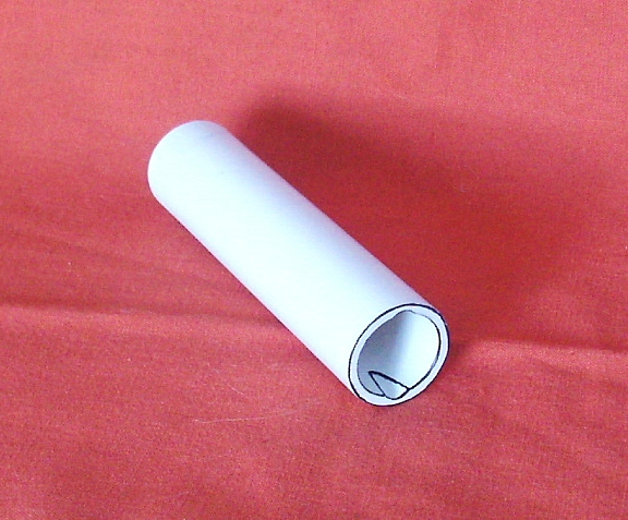
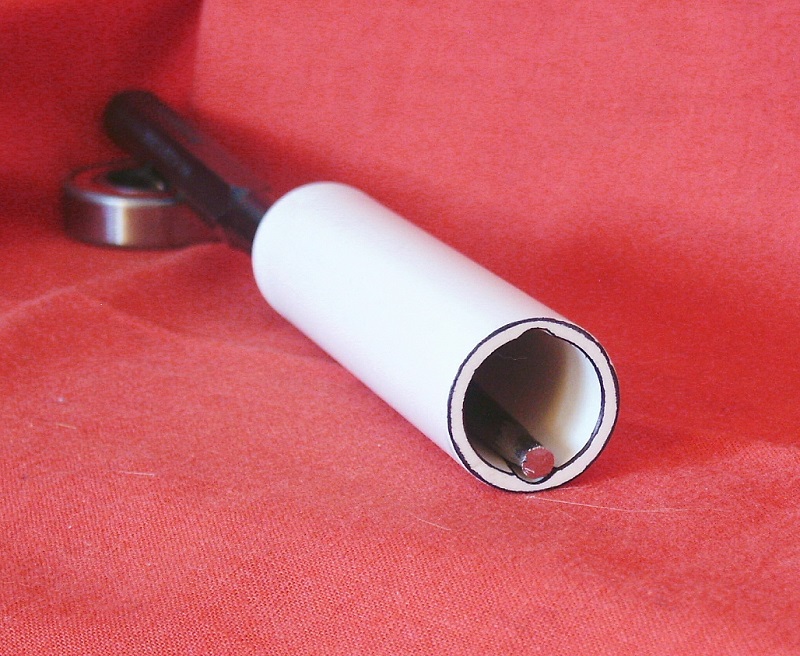
You only have to do this to one end of the Distance Collar. I recommend placing the notched end to the left side of ST1100 wheels, for consistency front and rear, and because the rear wheel's right side bearing is a double-row type. The double-row bearing will be easier to remove after the left side, single-row bearing is out.
~~~
Thank You again for your contribution Paul Kolbo, STOC #273 and John OoSTerhuis, STOC #1058
~~~
Wheel Bearing R&R Tip: Distance Collar Mod ( ST1100 )
If you've ever had difficulty removing an ST's wheel bearings, it's usually because the Distance Collar is so tightly wedged that you can't move it enough to get at the bearing properly. BTDT!...
While you've got the Distance Collar out, grind a couple of notches on the ID of one end so that whatever driver/drift/rod you are using will have better purchase on the backside of the inner race of the bearing you're pounding out. I don't have a Distance Collar handy so I used a piece of PVC pipe to simulate the real thing, and added some black marker for clarity:
You only have to do this to one end of the Distance Collar. I recommend placing the notched end to the left side of ST1100 wheels, for consistency front and rear, and because the rear wheel's right side bearing is a double-row type. The double-row bearing will be easier to remove after the left side, single-row bearing is out.
~~~
Thank You again for your contribution Paul Kolbo, STOC #273 and John OoSTerhuis, STOC #1058
#12
ST1100 Archive of Wisdom / How to replace the Water Pump ...
Last post by KoTAOW - June 28, 2018, 02:15:12 PMSubmitted by Alan Wilson, STOC #XXXX
Location:8 Grahamsdyke Road, Bo’Ness. West Lothian. EH51 9EG
Contact email: sales@happybikes.co.uk
Original article is located here: https://www.happybikes.co.uk/help/st1100_waterpump_bearing.htm
~~~
~~~
Parts available on ebay at this link: https://www.ebay.com/itm/HONDA-ST1100-A-PAN-EUROPEAN-WATER-PUMP-SEAL-AND-BEARING-KIT-90-02-B103-F952/382198697935?hash=item58fcd14fcf:g:VM0AAOSwbsBXiWpa
Price: GBP 49.99
Approximately US $66.15 (June 2018 )
~~~
You will need a small press for this, don’t try and use a vice or large mallet.
The hotter you get the pump casting the easier the bearing will press out. So remove the rubber band seal and idler bearing.
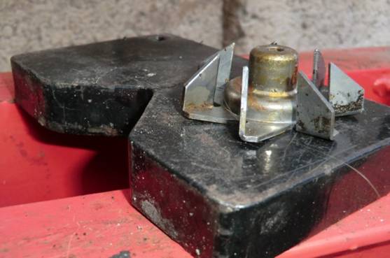
Decide now where and how you will support the casting in the press. It must be very close to the bearing.
Put the pump assembly into your kitchen oven and cook at 200 C for 10 mins, do that when the wife is out because it will smoke a bit.
Use gloves to remove.
Make sure the casting is well supported close to the bearing when you press, if you see the casting flex, stop because you haven’t got it supported well enough.
Read though these instructions a few times to make sure you understand the steps, they were written with mechanics in mind not for someone who thinks you press with an ironing board.
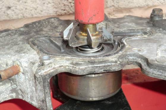
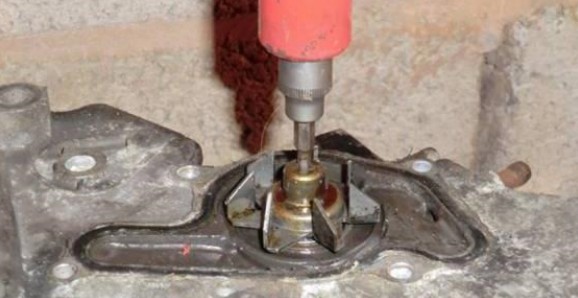
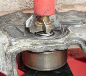
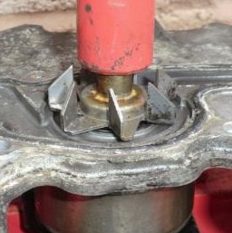
1. Press the bearing out using a 4 or 5 mm hex ½†or 3/8†socket drive.
Press though the hole in the fan end just as far as the length of the hex will allow you.
Any other attempt at removing the fan first will damage it
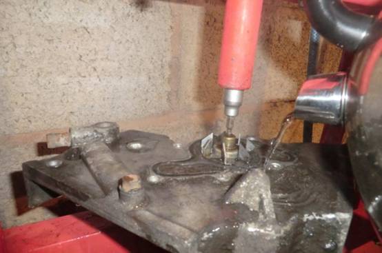
If you didn’t use the oven pouring some boiling water over the casting will loosen the bearing.
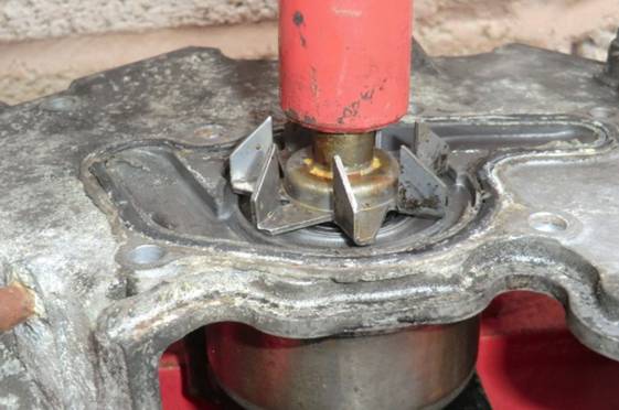
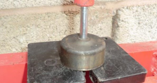
2. Once you have pressed the length of the hex key, raise the press and lift off the fan.
3. Finish off the pressing using a 1/4 "drive long 8mm socket, the bearing will fall out below.
4. Press or tap out the seal cup using a socket.
5. Press off the pulley from the bearing.
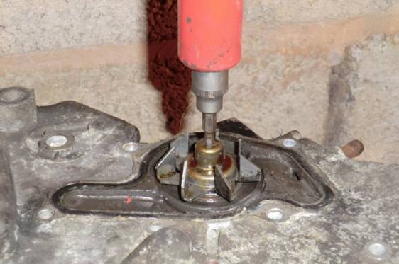
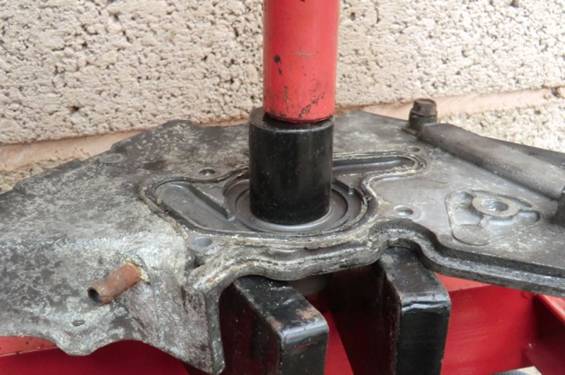
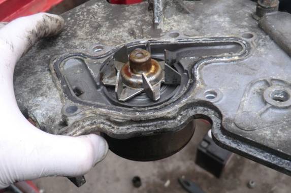
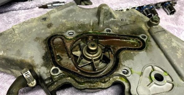
6. There are two bleed vent holes between the seal and the bearing, and the outside edge of the pump, make sure they are clear.
They tend to corrode closed due to the seal leaking and are a pain to clear but has to be done.
One is shown with a screwdriver, the other is show at about the 7 O’clock position
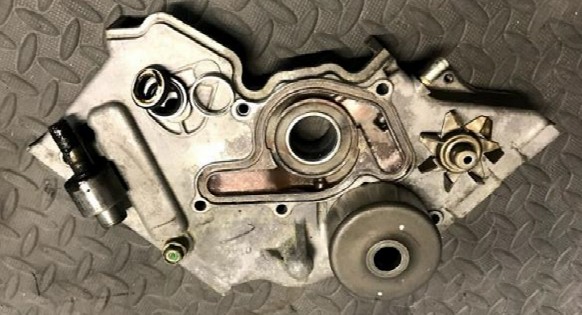
7. Reassemble, Press in the new bearing from the pulley side until the edge is flush with the casting. Use a 22mm socket.
8. Press in the new seal cup using a 27mm socket.
9. Press on the pulley wheel until the shaft protrudes by 1mm out of the pulley.
10. Put the fan onto a flat surface and check the blades are straight, they will probably be bent a very little so straighten them out.
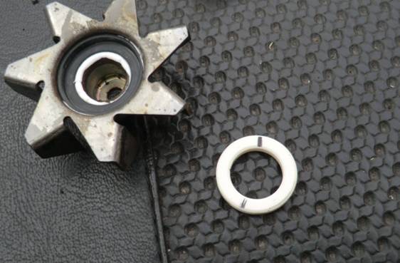
11. Remove the old seal and clean out the hole. Fit the new rubber seal into the fan using a little silicon sealant, this maybe a tight fit, looser is best so don't force, rub the rubber seal around the edge with some sand paper to achieve a "fall in fit" if required.
Fit the white ceramic washer, the side with the black marking goes against the rubber, don’t mix it up or the seal may not be water tight.
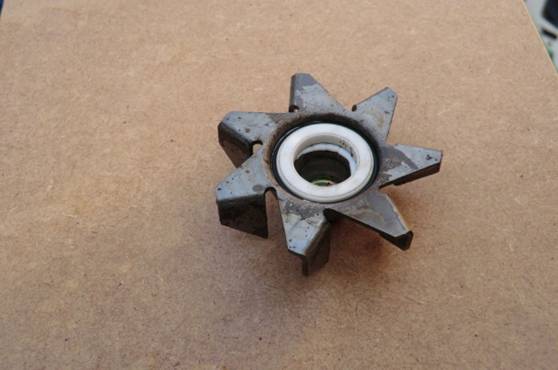
12. Press the fan fully onto the shaft.
13. Check the fan clearance, it should be about 1mm, closer is fine but higher risks the fan hitting the engine block. Make sure it turns freely.
It is lubed by the coolant so it will be a little stiff, don’t get or put oil on the ceramic surface, it can be contaminated and not seal.
~~~
Thank You again for your contribution Alan Wilson, STOC #XXXX
Location:8 Grahamsdyke Road, Bo’Ness. West Lothian. EH51 9EG
Contact email: sales@happybikes.co.uk
Original article is located here: https://www.happybikes.co.uk/help/st1100_waterpump_bearing.htm
~~~
How to replace the Water Pump Bearing and Seal ( ST1100 )
~~~
Parts available on ebay at this link: https://www.ebay.com/itm/HONDA-ST1100-A-PAN-EUROPEAN-WATER-PUMP-SEAL-AND-BEARING-KIT-90-02-B103-F952/382198697935?hash=item58fcd14fcf:g:VM0AAOSwbsBXiWpa
Price: GBP 49.99
Approximately US $66.15 (June 2018 )
~~~
Instructions:
You will need a small press for this, don’t try and use a vice or large mallet.
The hotter you get the pump casting the easier the bearing will press out. So remove the rubber band seal and idler bearing.
Decide now where and how you will support the casting in the press. It must be very close to the bearing.
Put the pump assembly into your kitchen oven and cook at 200 C for 10 mins, do that when the wife is out because it will smoke a bit.
Use gloves to remove.
Make sure the casting is well supported close to the bearing when you press, if you see the casting flex, stop because you haven’t got it supported well enough.
Read though these instructions a few times to make sure you understand the steps, they were written with mechanics in mind not for someone who thinks you press with an ironing board.
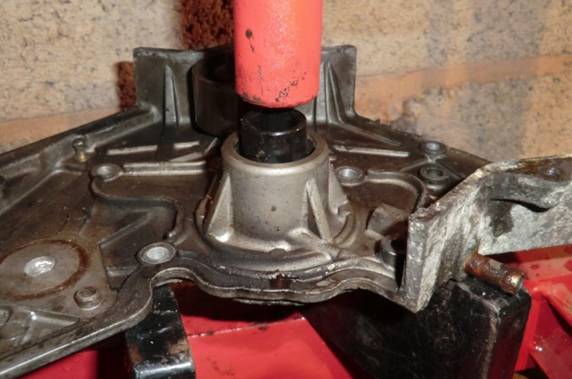
1. Press the bearing out using a 4 or 5 mm hex ½†or 3/8†socket drive.
Press though the hole in the fan end just as far as the length of the hex will allow you.
Any other attempt at removing the fan first will damage it
If you didn’t use the oven pouring some boiling water over the casting will loosen the bearing.
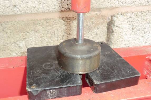
2. Once you have pressed the length of the hex key, raise the press and lift off the fan.
3. Finish off the pressing using a 1/4 "drive long 8mm socket, the bearing will fall out below.
4. Press or tap out the seal cup using a socket.
5. Press off the pulley from the bearing.
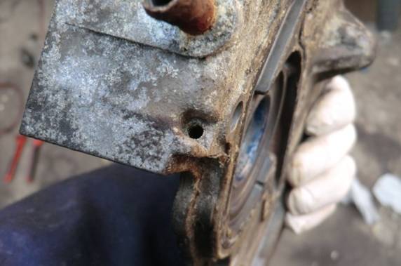
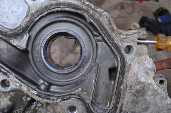
6. There are two bleed vent holes between the seal and the bearing, and the outside edge of the pump, make sure they are clear.
They tend to corrode closed due to the seal leaking and are a pain to clear but has to be done.
One is shown with a screwdriver, the other is show at about the 7 O’clock position
7. Reassemble, Press in the new bearing from the pulley side until the edge is flush with the casting. Use a 22mm socket.
8. Press in the new seal cup using a 27mm socket.
9. Press on the pulley wheel until the shaft protrudes by 1mm out of the pulley.
10. Put the fan onto a flat surface and check the blades are straight, they will probably be bent a very little so straighten them out.
11. Remove the old seal and clean out the hole. Fit the new rubber seal into the fan using a little silicon sealant, this maybe a tight fit, looser is best so don't force, rub the rubber seal around the edge with some sand paper to achieve a "fall in fit" if required.
Fit the white ceramic washer, the side with the black marking goes against the rubber, don’t mix it up or the seal may not be water tight.
12. Press the fan fully onto the shaft.
13. Check the fan clearance, it should be about 1mm, closer is fine but higher risks the fan hitting the engine block. Make sure it turns freely.
It is lubed by the coolant so it will be a little stiff, don’t get or put oil on the ceramic surface, it can be contaminated and not seal.
~~~
Thank You again for your contribution Alan Wilson, STOC #XXXX
#13
ST1100 Archive of Wisdom / Rebuilding the Water Pump ( ST...
Last post by KoTAOW - June 27, 2018, 10:26:09 PMSubmitted by Terry Smith, STOC #8901
~~~
Complete water pumps are unavailable for the early ST’s new, but I was able to find a vendor on
eBay, happybikes.co.uk who sells a rebuild kit for GBP68.99, shipped to anywhere.
Ebay store is located here: https://www.ebay.co.uk/str/happybikesshopforfastdelivery
Web page here: http://www.happybikes.co.uk/.
Some of the photos below are from the vendor’s website. The same kit can also be used on later model ST1100’s. The vendor (Alan) was helpful via text using the number on his website.
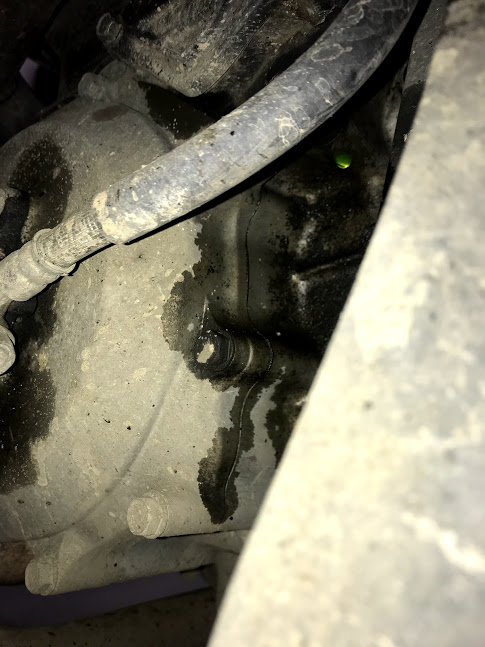
The water pump seal and/or the o-ring on the pump housing began leaking on my 28-year old bike
at around 125,000km.
The pulley and impellor get re-used, so need to be pressed out of the original housing.
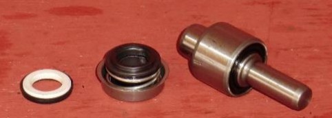
The parts supplied consisted of a new shaft and bearings, ceramic seal, stationary seal and rubber
seal for the impellor.
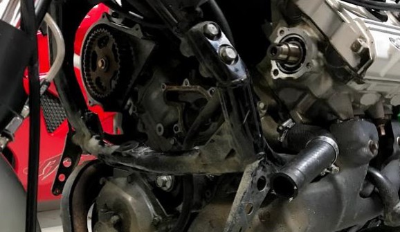
To access the pump, you will need to remove the bodywork, drain and remove the radiator, then
remove the timing belt covers and the timing belt, plus the tensioner and idler pulleys. You will also
need to remove one of the cam pulleys and the cover that bolts to the cylinder head (I did the left
side), without that you have no way of getting the pump housing out of the bike; you will probably
need a new gasket for this one (14525-MY3-000). I also ordered a new pump o-ring (19226-MT3-
000) and the idler pulley (14560-MT3-003) as that had a loose bearing.
Once the 7 bolts are removed the pump housing can be removed from the front of the engine, I
used a pry bar to get it moving. I disconnected the oil-cooler water hose at the cooler, plus the hose
guide that shares the case bolts, as it was impractical to get it off the water pump housing in place.
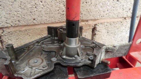
The instruction supplied by the vendor show the use of a hydraulic press to separate and reinstate
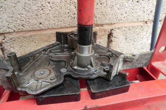
the parts, I don’t have access to a press so relied on using a large hammer.
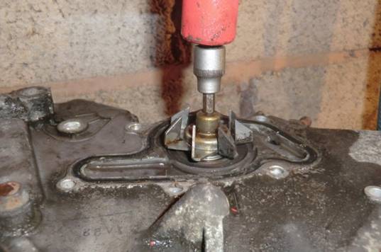
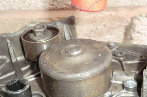
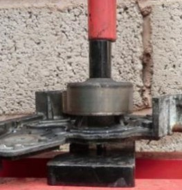
Firstly, support the pump housing well, close to the pulley, with the impellor facing up, then drive
the shaft/bearings out by pressing on the end of the shaft visible through the hole in the impellor. I
used a 5mm allen key bit mounted on the end of a short extension bar of my ½†socket set. The
socket on the end of the extension bar took a bit of a beating but is still usable.
This required some big hits to shift, and the vendor recommends heating the housing by pouring
boiling water onto it which will make the alloy parts expand (you could also heat it in an oven,
apparently that will stink up your kitchen, you have been warned).
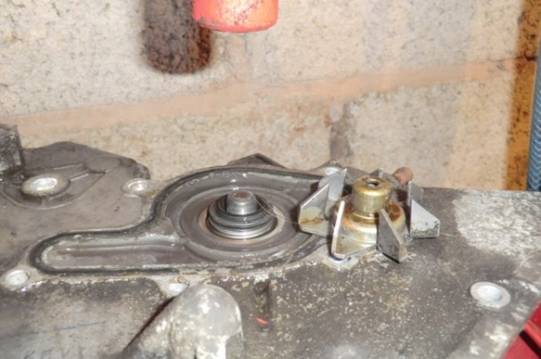
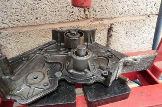
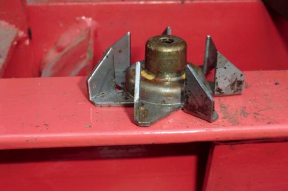
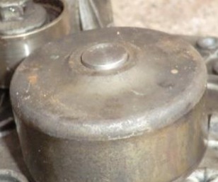
After the first bit of movement the impellor will make contact with the housing and then slide up off
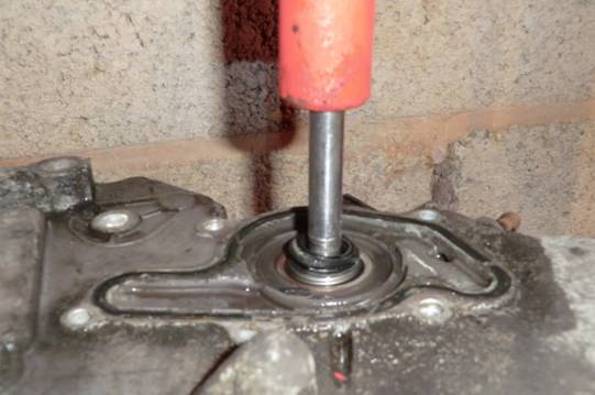
the shaft, and can be removed. You can switch to an 8mm socket bit and continue to drive the
shaft/bearings fully out of the housing.
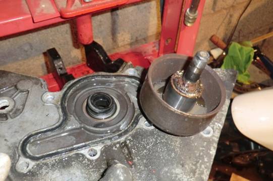
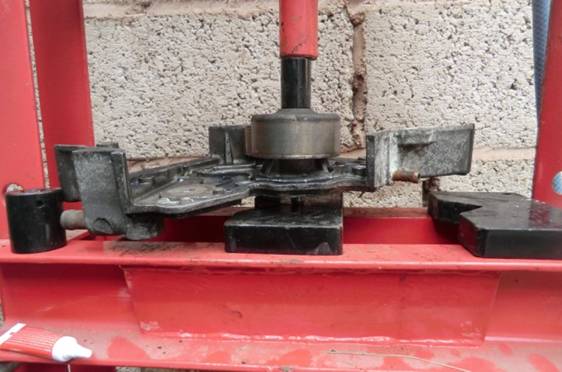
You now need to separate the pulley from the shaft; support the pulley well, then drive the shaft out
of the pulley fully using the 8mm diameter bit.
You can now drive the old seal out of the housing using a 16mm socket. I cleaned up the pulley
bearing housing with fine sandpaper to make reinstallation easier and added a little grease. I took
time to clean the pump housing fully as well. This includes the two weep holes at right angles to the
shaft axis.
I drove the new bearing and axle into the pump housing using a 22mm socket, until the surface of
bearing was flush with the edge of the housing. To make this easier I heated the pump housing with
a hot air gun, and chilled the bearing/shaft in my freezer first.
Flip the assembly over, and gently press the pump stationary seal into the housing using a 22mm
socket.
Now the pulley can be re-fitted, driven onto the shaft which I supported well from below so all the
load is transferred to the support, not through the bearings. The pulley should be driven until the
shaft projects by 1mm.
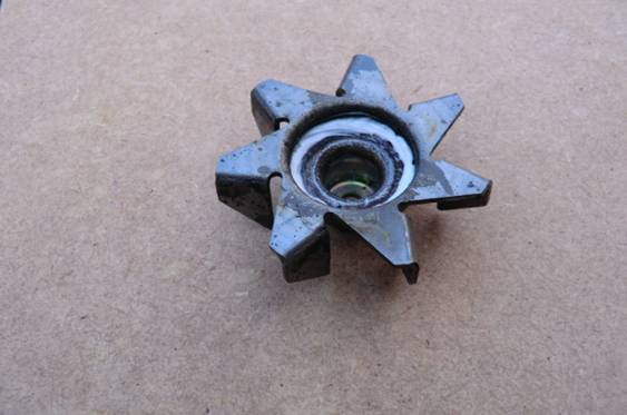
The impellor should be checked/trued for flatness in case the removal process bent it; mine was
fine.
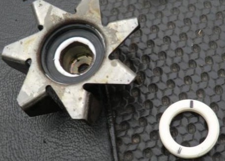
The rubber seal is now fitted into the impellor hub with a small amount of silicon sealer, then the
ceramic seal is fitted. The seal has a glossy side, and a machined matte side; the matte side should
face the stationary seal in the pump housing. Don’t apply any lubricant other than coolant to this
seal.
The impellor is now placed on the shaft and driven home, again the shaft needs to be supported
from below so no force is imparted to the bearing. There was a final clearance of about 1mm
between the pump housing and the impellor.
And…you’re done.
You will find that the seal is a little stiff (it is lubricated by coolant) so the impellor won’t turn that
freely. Don’t panic.
~~~
Thank You again for your contribution Terry Smith, STOC #8901
~~~
Rebuilding the Water Pump ( ST1100 )
Complete water pumps are unavailable for the early ST’s new, but I was able to find a vendor on
eBay, happybikes.co.uk who sells a rebuild kit for GBP68.99, shipped to anywhere.
Ebay store is located here: https://www.ebay.co.uk/str/happybikesshopforfastdelivery
Web page here: http://www.happybikes.co.uk/.
Some of the photos below are from the vendor’s website. The same kit can also be used on later model ST1100’s. The vendor (Alan) was helpful via text using the number on his website.
Instructions:
The water pump seal and/or the o-ring on the pump housing began leaking on my 28-year old bike
at around 125,000km.
The pulley and impellor get re-used, so need to be pressed out of the original housing.
The parts supplied consisted of a new shaft and bearings, ceramic seal, stationary seal and rubber
seal for the impellor.
To access the pump, you will need to remove the bodywork, drain and remove the radiator, then
remove the timing belt covers and the timing belt, plus the tensioner and idler pulleys. You will also
need to remove one of the cam pulleys and the cover that bolts to the cylinder head (I did the left
side), without that you have no way of getting the pump housing out of the bike; you will probably
need a new gasket for this one (14525-MY3-000). I also ordered a new pump o-ring (19226-MT3-
000) and the idler pulley (14560-MT3-003) as that had a loose bearing.
Once the 7 bolts are removed the pump housing can be removed from the front of the engine, I
used a pry bar to get it moving. I disconnected the oil-cooler water hose at the cooler, plus the hose
guide that shares the case bolts, as it was impractical to get it off the water pump housing in place.
The instruction supplied by the vendor show the use of a hydraulic press to separate and reinstate
the parts, I don’t have access to a press so relied on using a large hammer.
Firstly, support the pump housing well, close to the pulley, with the impellor facing up, then drive
the shaft/bearings out by pressing on the end of the shaft visible through the hole in the impellor. I
used a 5mm allen key bit mounted on the end of a short extension bar of my ½†socket set. The
socket on the end of the extension bar took a bit of a beating but is still usable.
This required some big hits to shift, and the vendor recommends heating the housing by pouring
boiling water onto it which will make the alloy parts expand (you could also heat it in an oven,
apparently that will stink up your kitchen, you have been warned).
After the first bit of movement the impellor will make contact with the housing and then slide up off
the shaft, and can be removed. You can switch to an 8mm socket bit and continue to drive the
shaft/bearings fully out of the housing.
You now need to separate the pulley from the shaft; support the pulley well, then drive the shaft out
of the pulley fully using the 8mm diameter bit.
You can now drive the old seal out of the housing using a 16mm socket. I cleaned up the pulley
bearing housing with fine sandpaper to make reinstallation easier and added a little grease. I took
time to clean the pump housing fully as well. This includes the two weep holes at right angles to the
shaft axis.
I drove the new bearing and axle into the pump housing using a 22mm socket, until the surface of
bearing was flush with the edge of the housing. To make this easier I heated the pump housing with
a hot air gun, and chilled the bearing/shaft in my freezer first.
Flip the assembly over, and gently press the pump stationary seal into the housing using a 22mm
socket.
Now the pulley can be re-fitted, driven onto the shaft which I supported well from below so all the
load is transferred to the support, not through the bearings. The pulley should be driven until the
shaft projects by 1mm.
The impellor should be checked/trued for flatness in case the removal process bent it; mine was
fine.
The rubber seal is now fitted into the impellor hub with a small amount of silicon sealer, then the
ceramic seal is fitted. The seal has a glossy side, and a machined matte side; the matte side should
face the stationary seal in the pump housing. Don’t apply any lubricant other than coolant to this
seal.
The impellor is now placed on the shaft and driven home, again the shaft needs to be supported
from below so no force is imparted to the bearing. There was a final clearance of about 1mm
between the pump housing and the impellor.
And…you’re done.
You will find that the seal is a little stiff (it is lubricated by coolant) so the impellor won’t turn that
freely. Don’t panic.
~~~
Thank You again for your contribution Terry Smith, STOC #8901
#14
ST1100 Archive of Wisdom / Electric Fuel Pump Option ( ST...
Last post by KoTAOW - March 26, 2018, 06:41:49 PMContributed by Dale Isley, STOC #5341.
~~~
I thought I might post my solution to replacing a dead fuel pump on an ST1100. A lot of people have used Carter or Honda Automotive pumps and attached them to the stock fuel pump assembly. I decided to go electric and mounted it to replace the Auto Fuel Valve that many have already removed from their systems.
In this application you simply leave the dead pump and everything in your fuel tank alone. The Facet pump will use the old dead tank set up as a pick up tube.

NAPA has a part number 610-3021 which is the Facet Posi-Flow pump and even came branded that way. Rated at 1psi-2psi at 7gph (this is the lowest rating... some sites have it rated as much as 1.5psi-2.5psi at 25gph) I thought it would be a better fit that the 40178, 40177, etc, etc. Since it is a Posi-Flow it is rounder than the Cube and should fit easier as well. It is about $70 - $80 at the time of my purchase through NAPA. It can be had for a bit less online, but I wasn't willing to wait for the little savings once shipping was added to their lower price.
The Facet Posi-Flow page here: http://motor-components.com/shop/oem/#posi-flo shows it as the 60304, rated on the Facet site as 1psi-2psi 15gph with a 50" wet lift.

I fabricated this bracket and painted it black. This will locate the pump on the right side of the air filter housing using the bracket from the Auto Fuel Valve.

You will need to add a 90 degree fitting to the outflow side. The stock outflow fuel line has a 90 degree bend molded into it. You will be removing the molded bend from the fuel line and once cut you will attach it to the fitting. There is a 45 degree fitting on the inflow toward the tank, where I inserted an inline fuel filter. The Fuel Filter is NAPA Part number 610-1085 and it is a Balkamp part number FEP735.
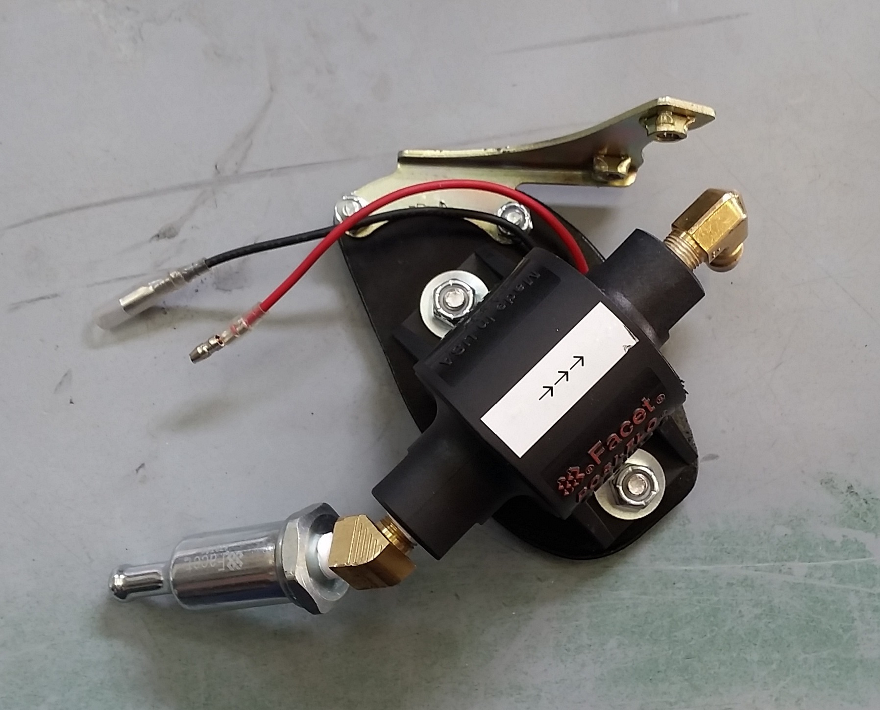
This is the bracket with pump and fittings attached to the Auto Fuel Valve bracket ready to bolt to the air filter housing.


A few pictures showing the position of everything in place.

Pump power was pulled from the spade connector going to the stock pump.

Here is a picture of the new pump, wiring, and you'll notice I wrapped the inline fuel filter in some closed cell foam with a zip tie. This is to protect the plastic once the air filter cover is installed.

Tupperware going back on... this picture was taken before I wrapped the electical with protective plastic loom, which you can see on the previous picture.

While it is all apart, remove the rubber insert around your fuel cap, drill a hole through the bottom of the idle adjuster hold down, and thread a zip to hold that sucker. Makes turning the knob to adjust your idle SO EASY!
I've been running this configuration for about a year, over 8k miles, and have not had any issues.
As I said, just an option. I can carry an extra fuel pump and filter in my under seat storage with my tools and be able to change it out on the road if failure occurs.
~~~
Thank You again for your contribution ]Dale Isley, STOC #5341
~~~
Electric Fuel Pump Option ( ST1100 )
I thought I might post my solution to replacing a dead fuel pump on an ST1100. A lot of people have used Carter or Honda Automotive pumps and attached them to the stock fuel pump assembly. I decided to go electric and mounted it to replace the Auto Fuel Valve that many have already removed from their systems.
In this application you simply leave the dead pump and everything in your fuel tank alone. The Facet pump will use the old dead tank set up as a pick up tube.
NAPA has a part number 610-3021 which is the Facet Posi-Flow pump and even came branded that way. Rated at 1psi-2psi at 7gph (this is the lowest rating... some sites have it rated as much as 1.5psi-2.5psi at 25gph) I thought it would be a better fit that the 40178, 40177, etc, etc. Since it is a Posi-Flow it is rounder than the Cube and should fit easier as well. It is about $70 - $80 at the time of my purchase through NAPA. It can be had for a bit less online, but I wasn't willing to wait for the little savings once shipping was added to their lower price.
The Facet Posi-Flow page here: http://motor-components.com/shop/oem/#posi-flo shows it as the 60304, rated on the Facet site as 1psi-2psi 15gph with a 50" wet lift.
I fabricated this bracket and painted it black. This will locate the pump on the right side of the air filter housing using the bracket from the Auto Fuel Valve.
You will need to add a 90 degree fitting to the outflow side. The stock outflow fuel line has a 90 degree bend molded into it. You will be removing the molded bend from the fuel line and once cut you will attach it to the fitting. There is a 45 degree fitting on the inflow toward the tank, where I inserted an inline fuel filter. The Fuel Filter is NAPA Part number 610-1085 and it is a Balkamp part number FEP735.
This is the bracket with pump and fittings attached to the Auto Fuel Valve bracket ready to bolt to the air filter housing.
A few pictures showing the position of everything in place.
Pump power was pulled from the spade connector going to the stock pump.
Here is a picture of the new pump, wiring, and you'll notice I wrapped the inline fuel filter in some closed cell foam with a zip tie. This is to protect the plastic once the air filter cover is installed.
Tupperware going back on... this picture was taken before I wrapped the electical with protective plastic loom, which you can see on the previous picture.
While it is all apart, remove the rubber insert around your fuel cap, drill a hole through the bottom of the idle adjuster hold down, and thread a zip to hold that sucker. Makes turning the knob to adjust your idle SO EASY!
I've been running this configuration for about a year, over 8k miles, and have not had any issues.
As I said, just an option. I can carry an extra fuel pump and filter in my under seat storage with my tools and be able to change it out on the road if failure occurs.
~~~
Thank You again for your contribution ]Dale Isley, STOC #5341
#15
ST1300 Archive of Wisdom / LED Headlight Conversion ( ST1...
Last post by KoTAOW - January 09, 2018, 02:03:44 PMSubmitted by aka JayBear, STOC #XXXX
Original posting link: www.st-owners.com
~~~
How many ST riders does it take to change a light bulb[emoji47]
Hello fellow ST riders!
If you're trying to figure out how to install your new LED headlights then you have come to the right place. I recently changed out the lighting on the front of my ST1300 to all LEDs and realized information on the process was scattered all over so I decided to document my entire process by taking photos along the way. My hope is that this guide will help you to visualize the process and help you understand the mechanisms involved so that you can spend less time fumbling around and looking all over the threads for info.
Disclaimer: I am not a mechanic, electrical engineer, or a rocket scientist (go figure)! I am just an average DIY-er so use this information accordingly. Enough chit-chat, let's get to it!
BACKGROUND INFO AND SPECS
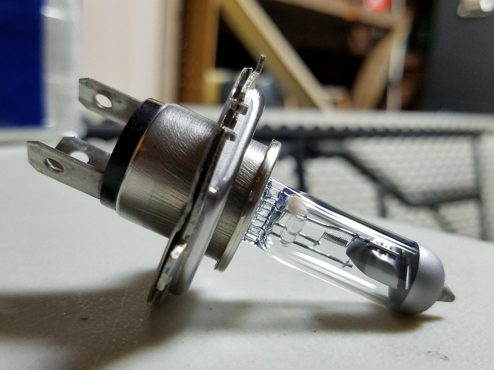
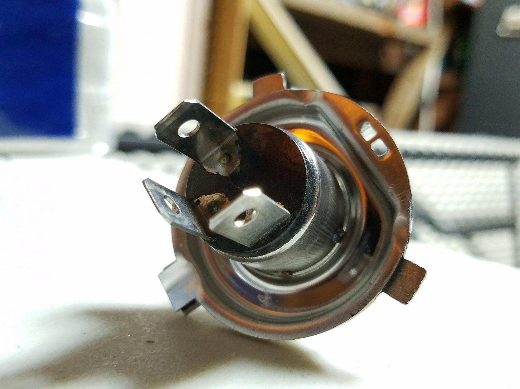
It is important to note that the tabs on the OEM bulb and the notches on the OEM housing do not have the same angle as an aftermarket H4 bulb (see photo below for comparison).
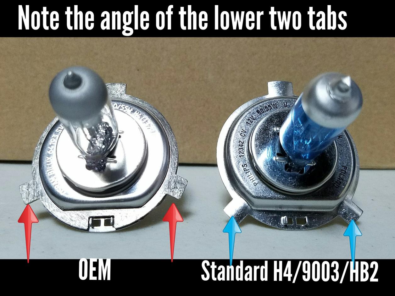
Notice the bottom two tabs on the OEM bulb are more spread out. Because of this you will need to modify the new bulb.
Common solutions are
***SIDE NOTE***
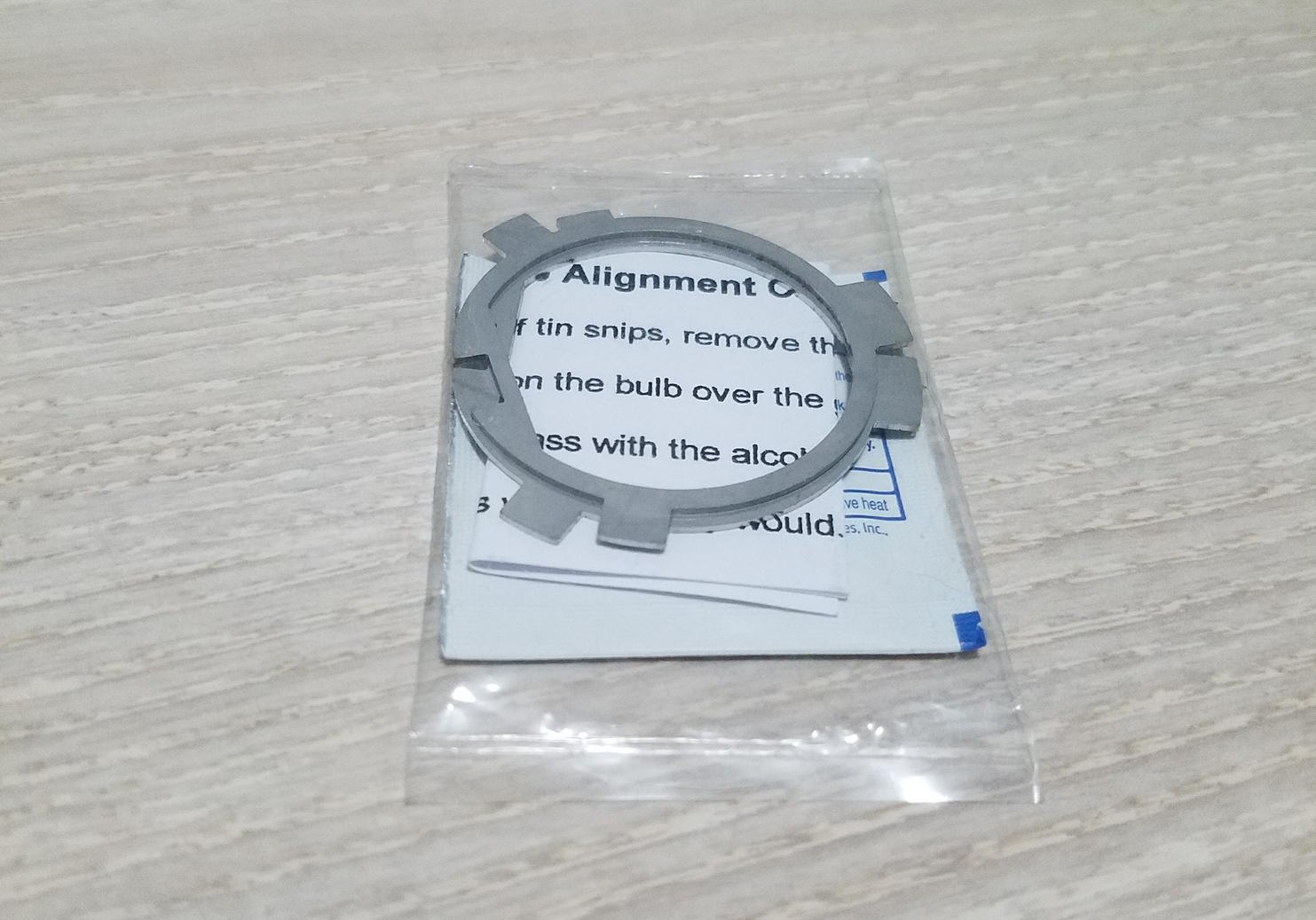
WHAT ARE SHIMS? They are metal rings cut to match the OEM tab angle. You just slip them on over the bulb so that you can lock them in place. Although not required for this project I want to share the info here.
Next item is how to access the bulbs. I used option #3 but other common solutions are (see images)
HEADLIGHT REPLACEMENT
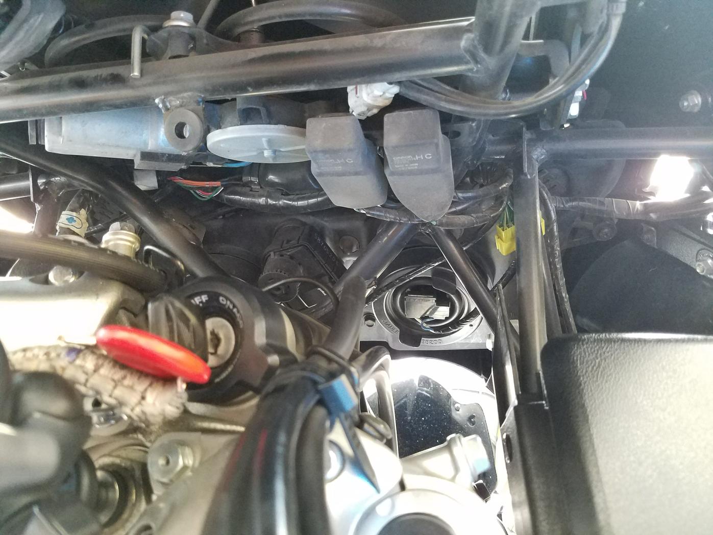
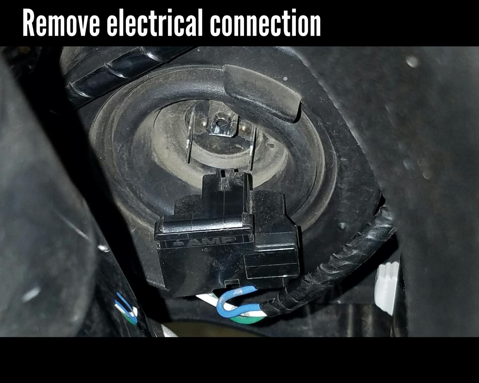
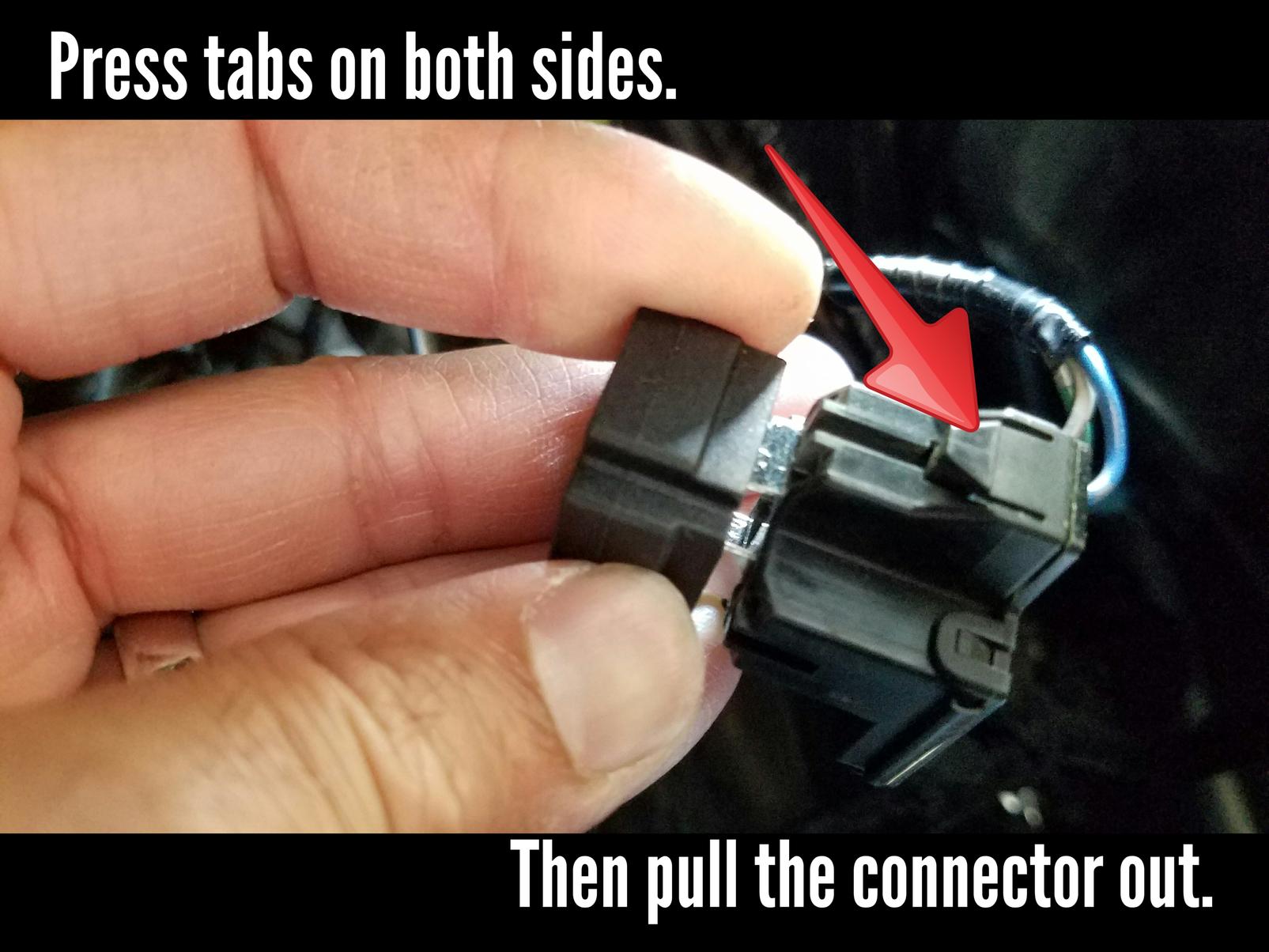
Locate the headlight. You will see a big round rubber boot with an electrical connector in the middle. You need to remove this connector. To do this you need to press down on the tabs located on either side of the connector (see image). You may need to dig your fingers into the boot a little bit to reach these tabs. You are disconnecting the harness from the bulb so you should only have to pull straight out but some wiggling may be required.
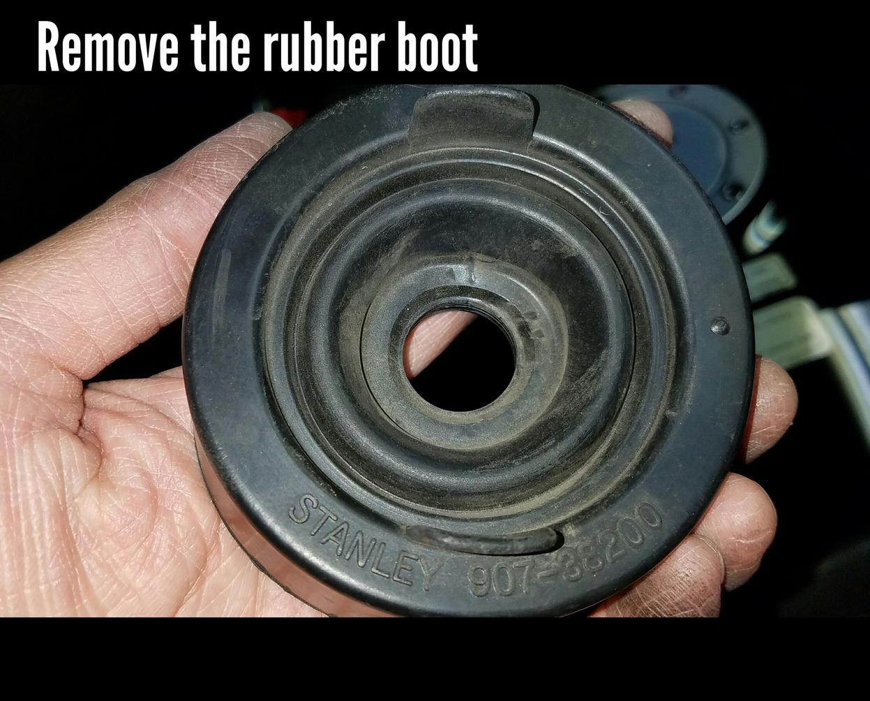
Once you have the connector from the wiring harness out, remove the rubber boot. Just grab from the edges and pull/peel back.
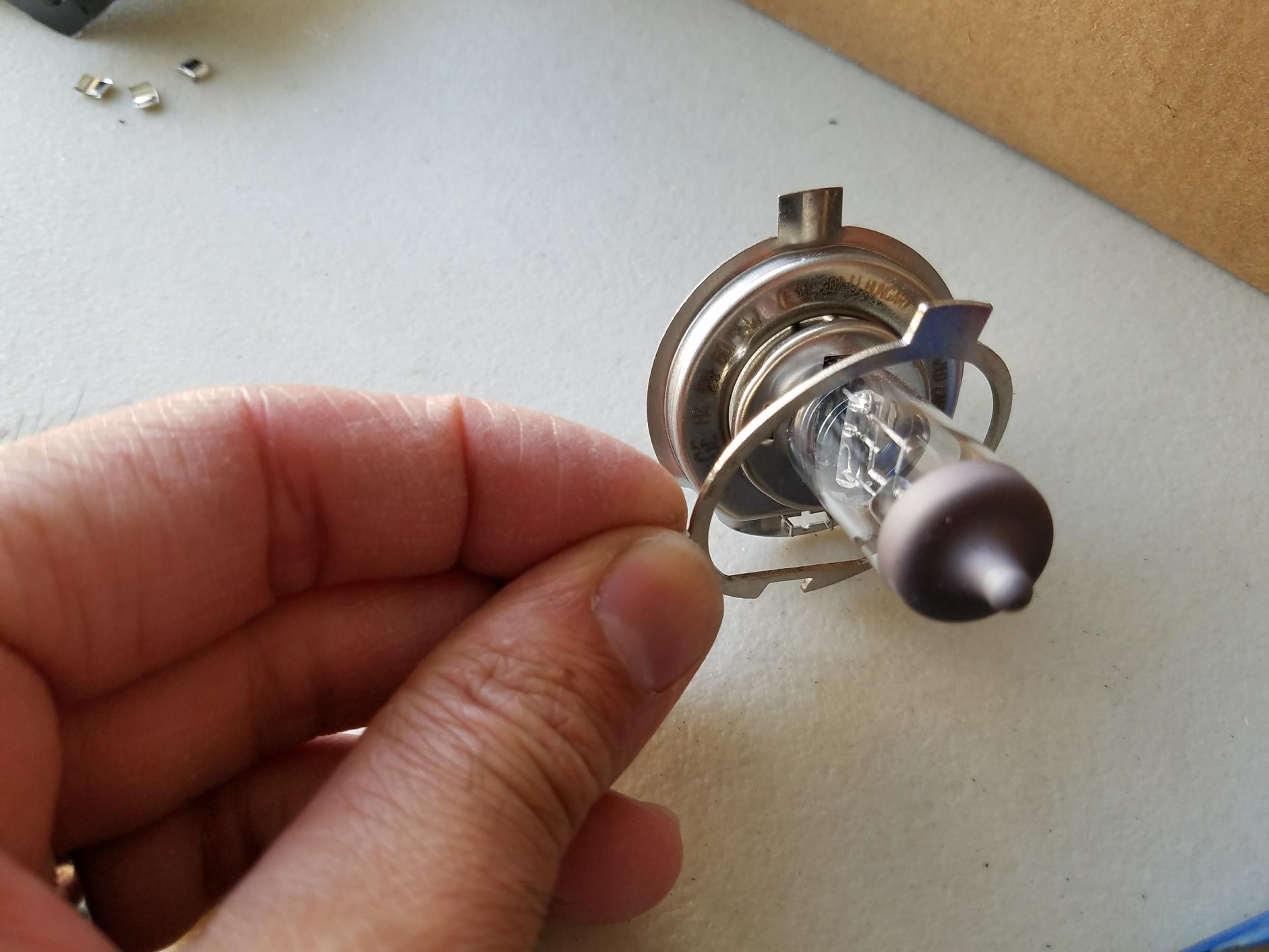
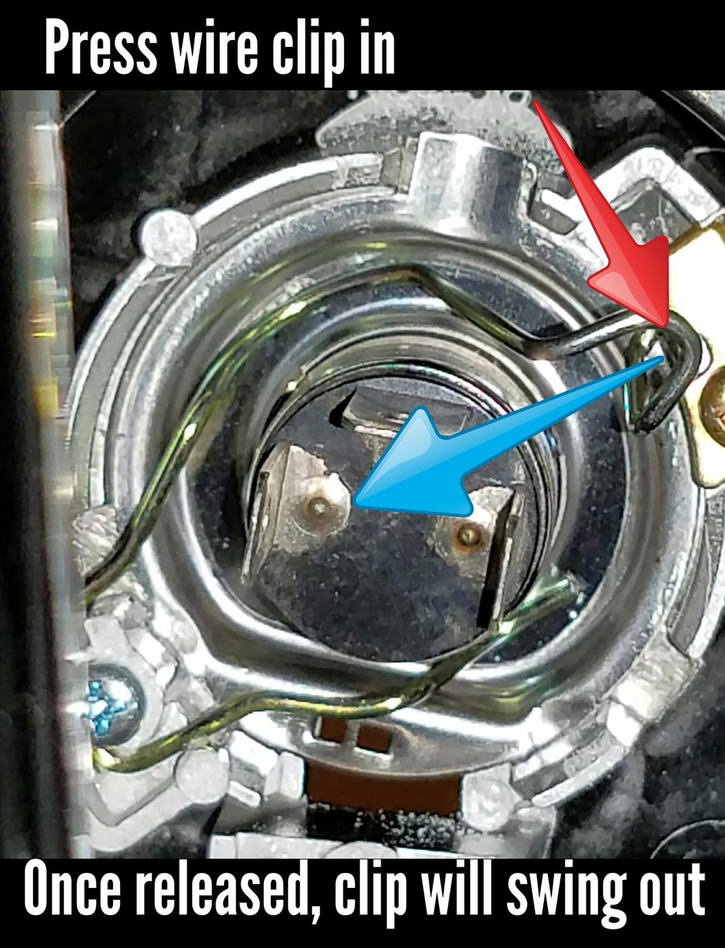
When the boot is off it will reveal the wire clip and the bulb. Now unlatch the wire clip, or bail clip, by pushing in with your thumb and turning slightly. The clip will unhook and swing open to free the bulb from the housing.
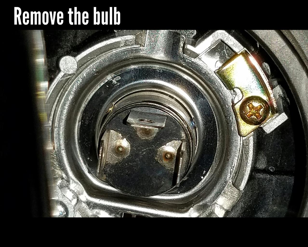
Then remove the bulb. Just pull straight out. Be careful not to let your fingers touch the glass if you plan on keeping the bulbs. If you do accidentally touch the glass then use a small amount of rubbing alcohol to clean it.
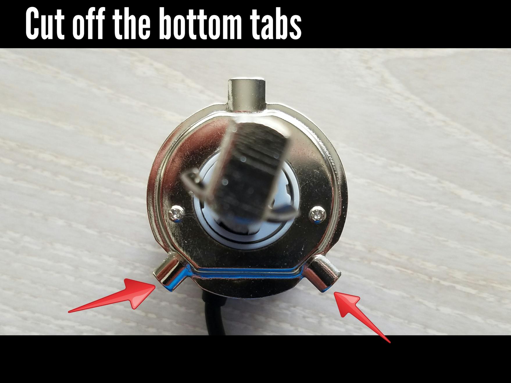
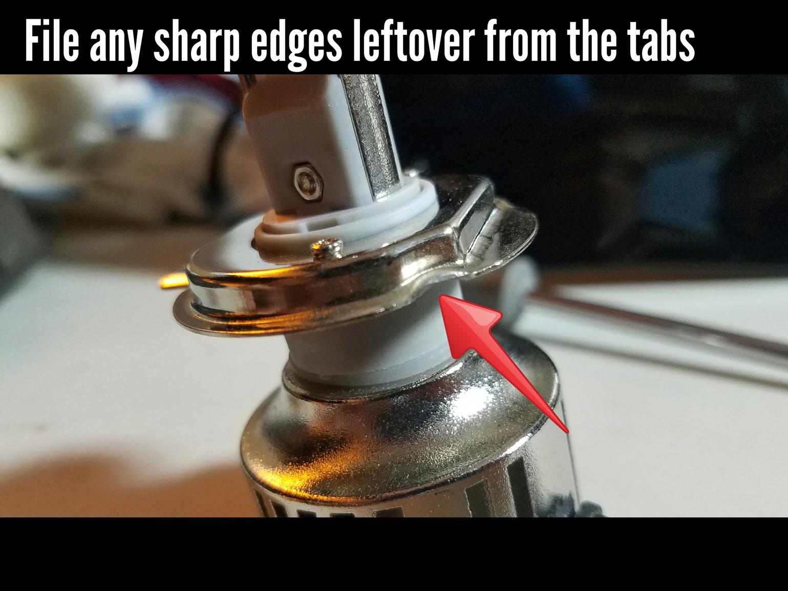
Now before you insert the new LED bulb you will need to modify it as mentioned earlier. Choose your weapon. I used a Dremel with a metal cutting wheel bit to cut and file off the lower two tabs.
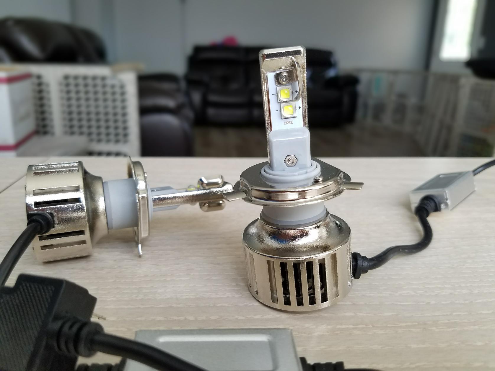
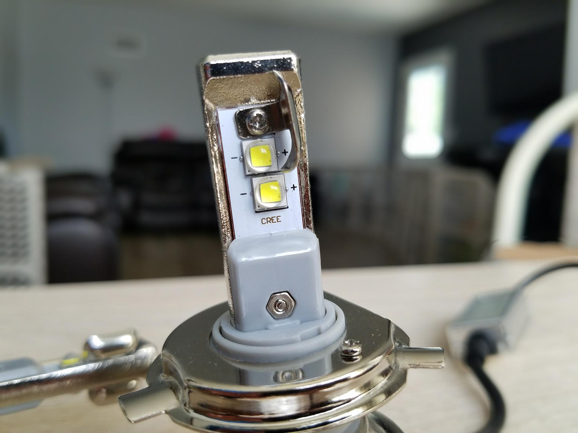
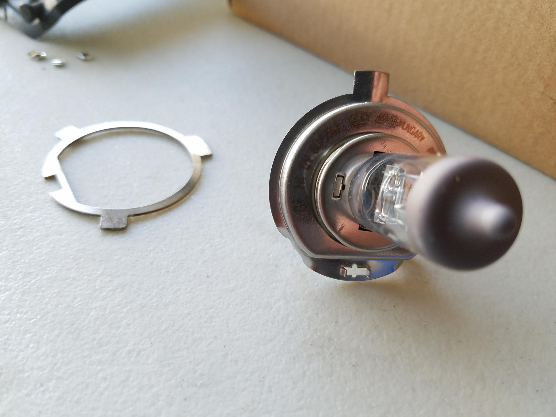
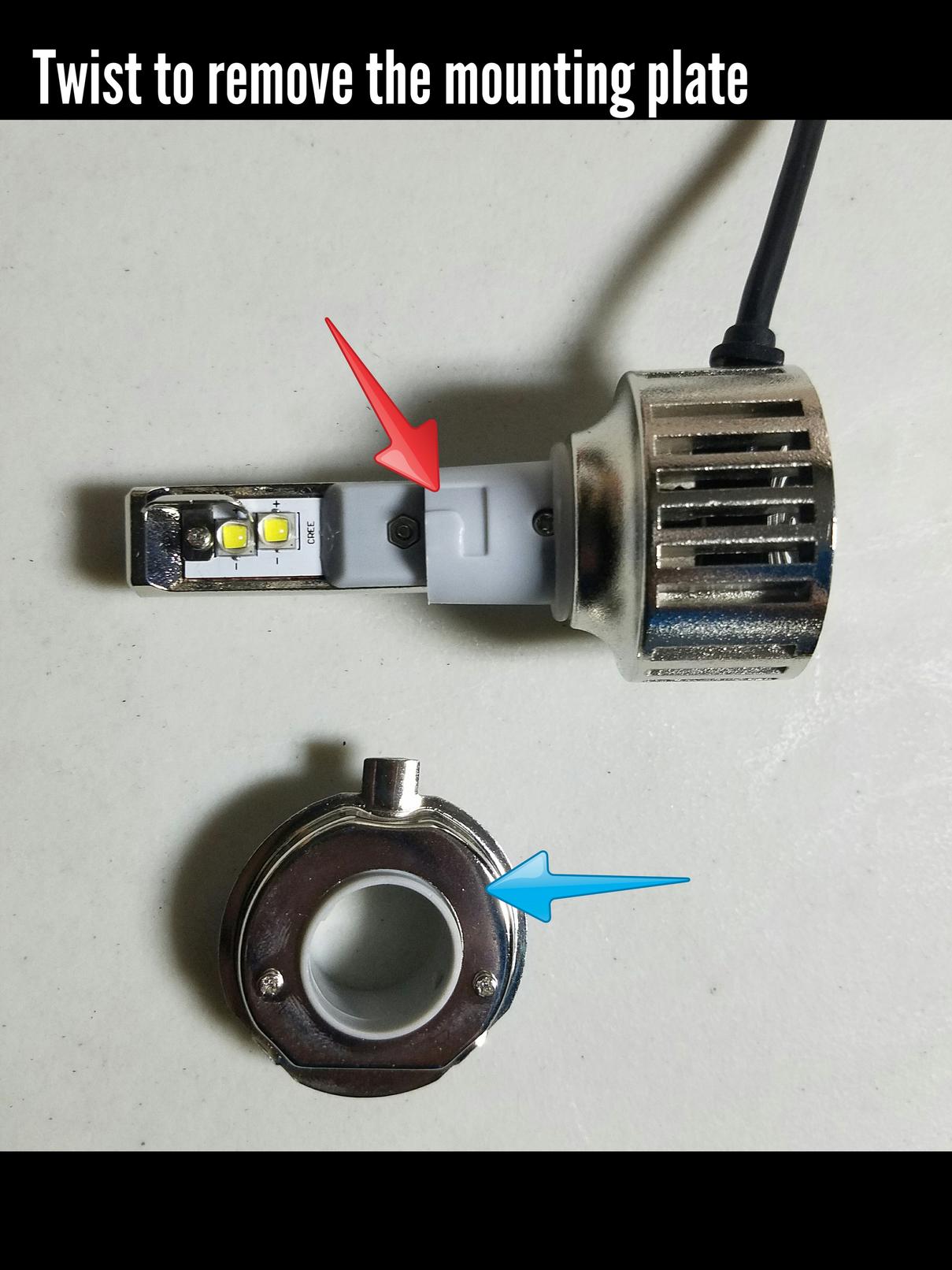
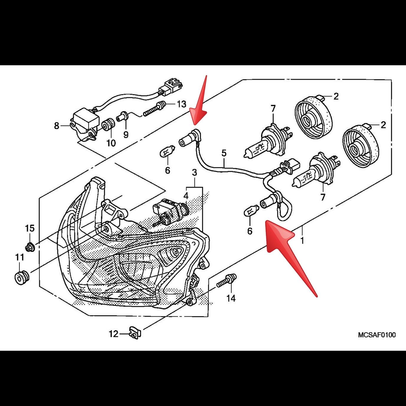
You need to know that the mounting plate (blue arrow, see image) that has the three tabs is removable. Just hold the plate with one hand the the fan with your other hand and twist. That will release the plate.
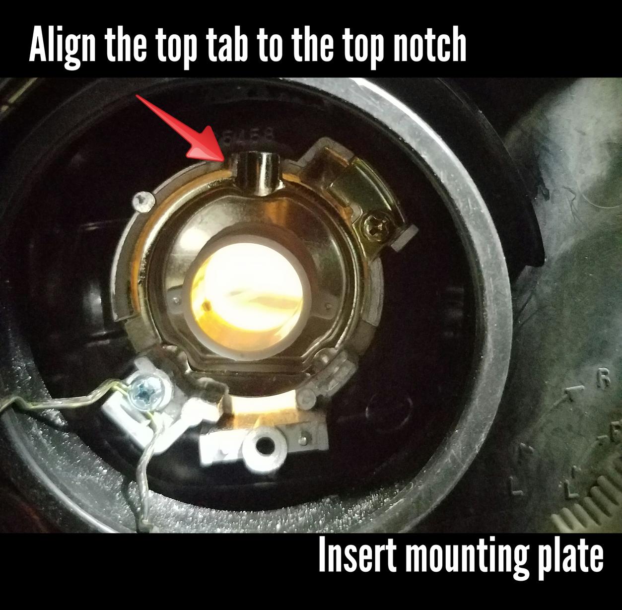
Now take the mounting plate (blue arrow, see image) and insert into the headlight housing by itself. Do not attach it to the bulb or else it will not fit! It will all make sense later. You must align the top tab with the notch in the housing (see image).
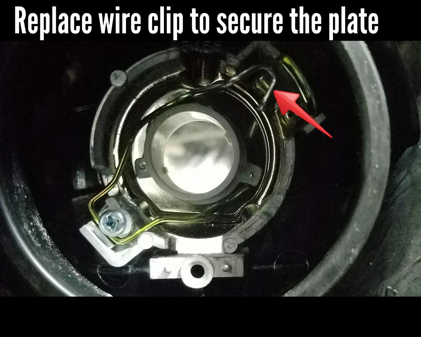
When you have the mounting plate inserted re-insert the wire clip to hold it down. This might take a while
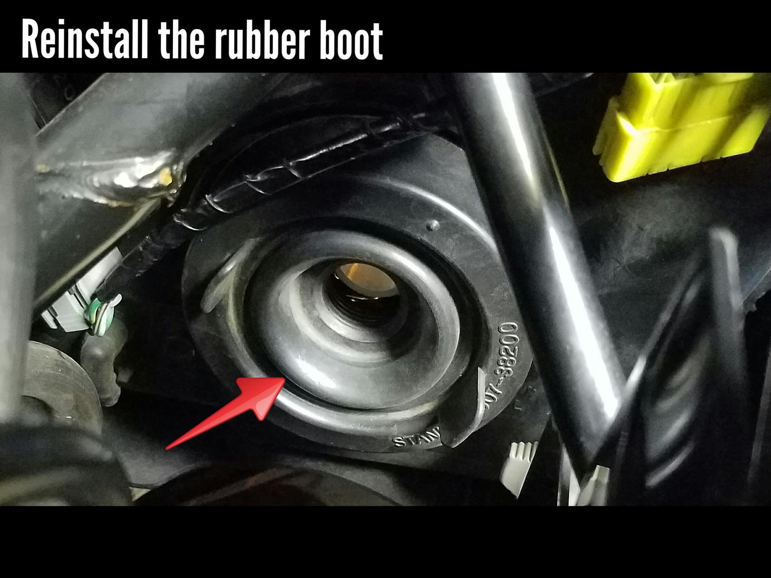
Now that the clip is back in put the rubber boot back on. Still no bulb should be inserted! I have seen posts where people leave the rubber boot off or even cut it up to make the hole wider but this is not required.
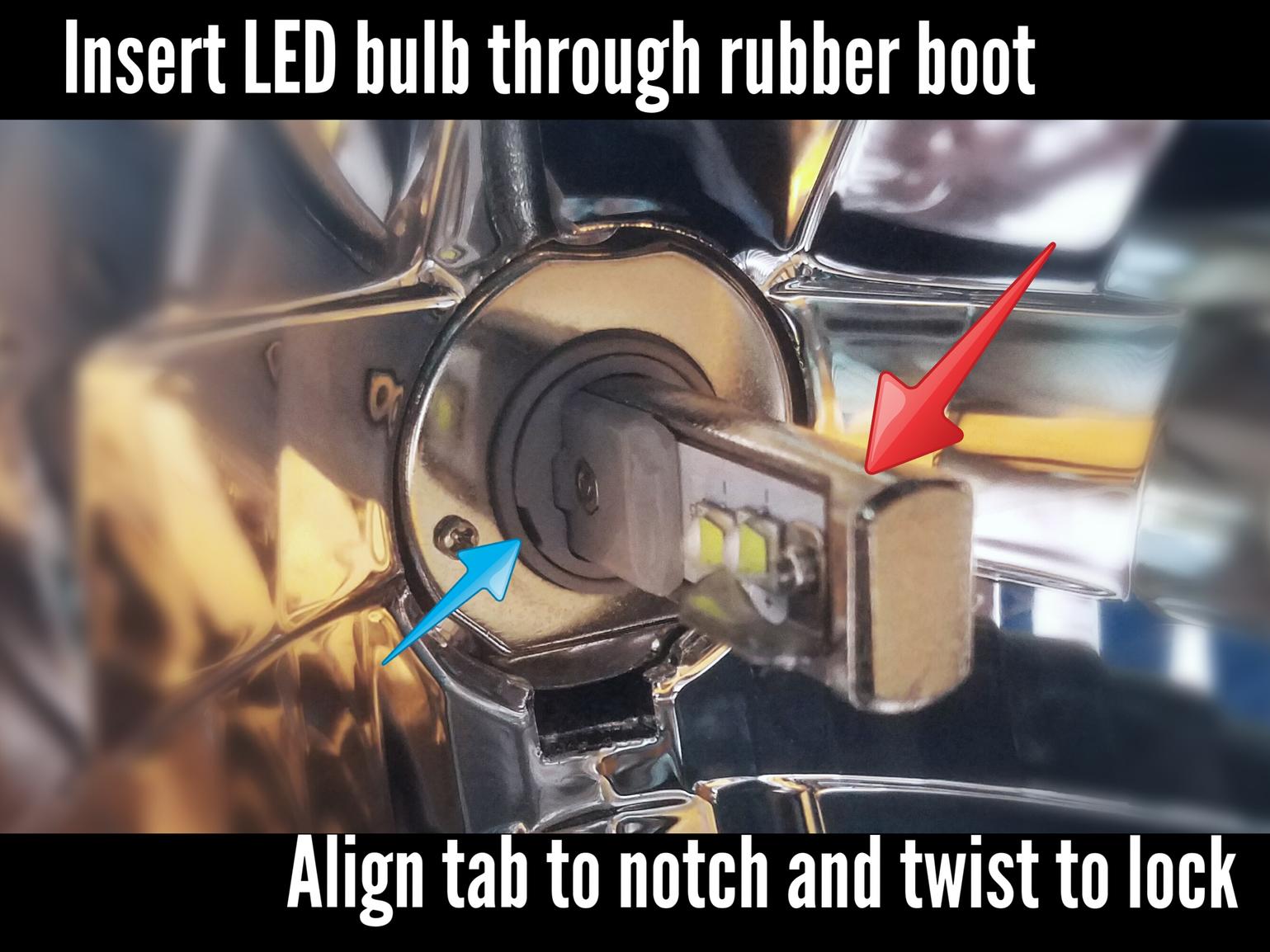
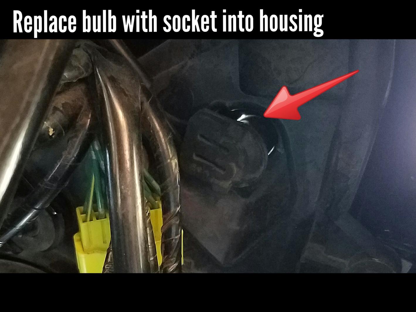
Okay, now you can insert the LED bulb in through the rubber boot. Remember those notches on the bulb from when you removed the mounting plate? Well you need to align them so that you can insert the bulb and then twist to lock it back in place. It will help to look through the front of the housing when you insert the bulb. Look for the notch to help you with the alignment (blue arrow, see image).
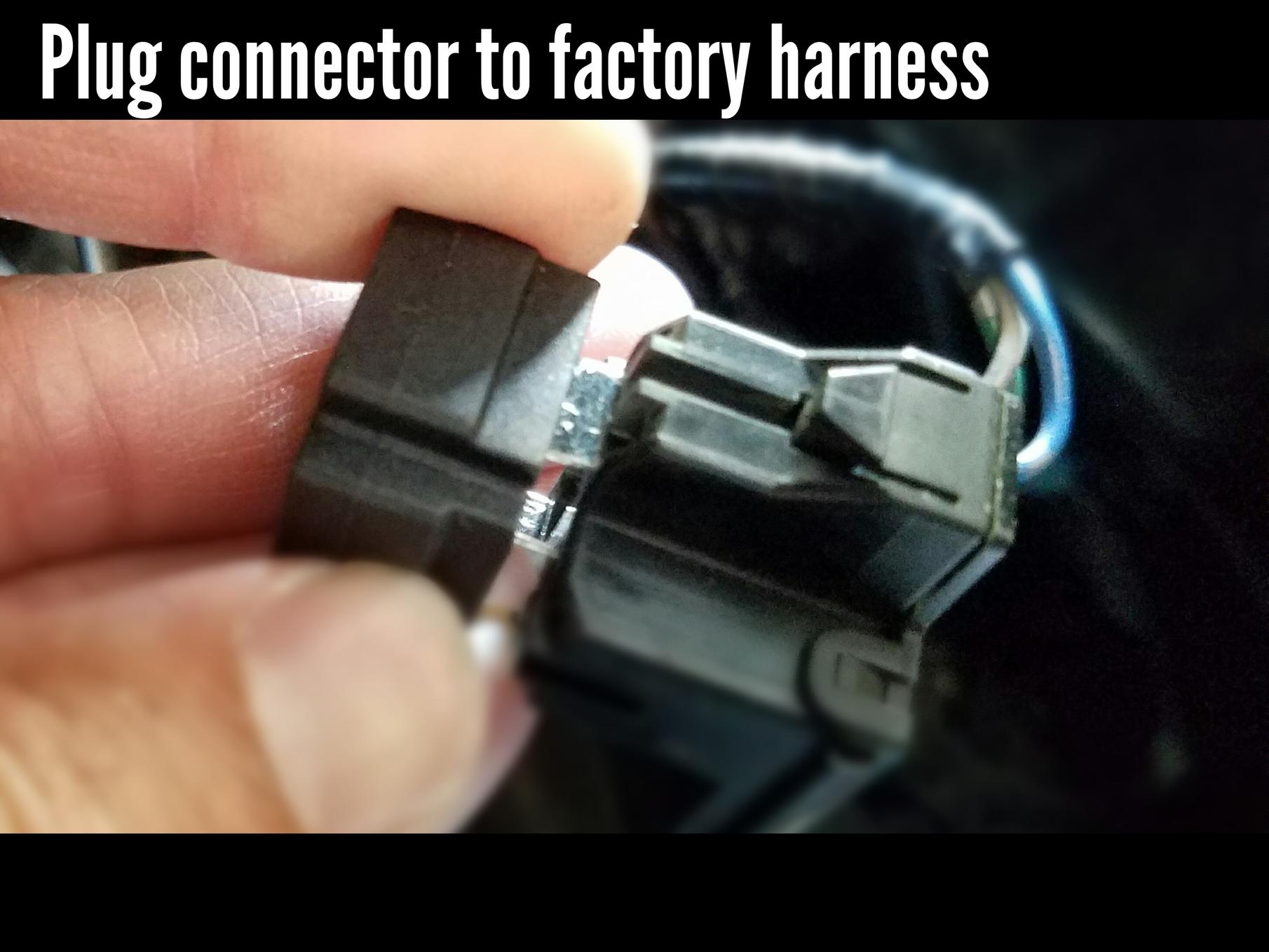
After you have the bulb locked in you're almost done. Just plug the electrical connector to the new bulb and tuck away and zip-tie the wires and the LED driver (ballast/box thing). I tied them off to the side so that it would not interfere when turning the handle bars.
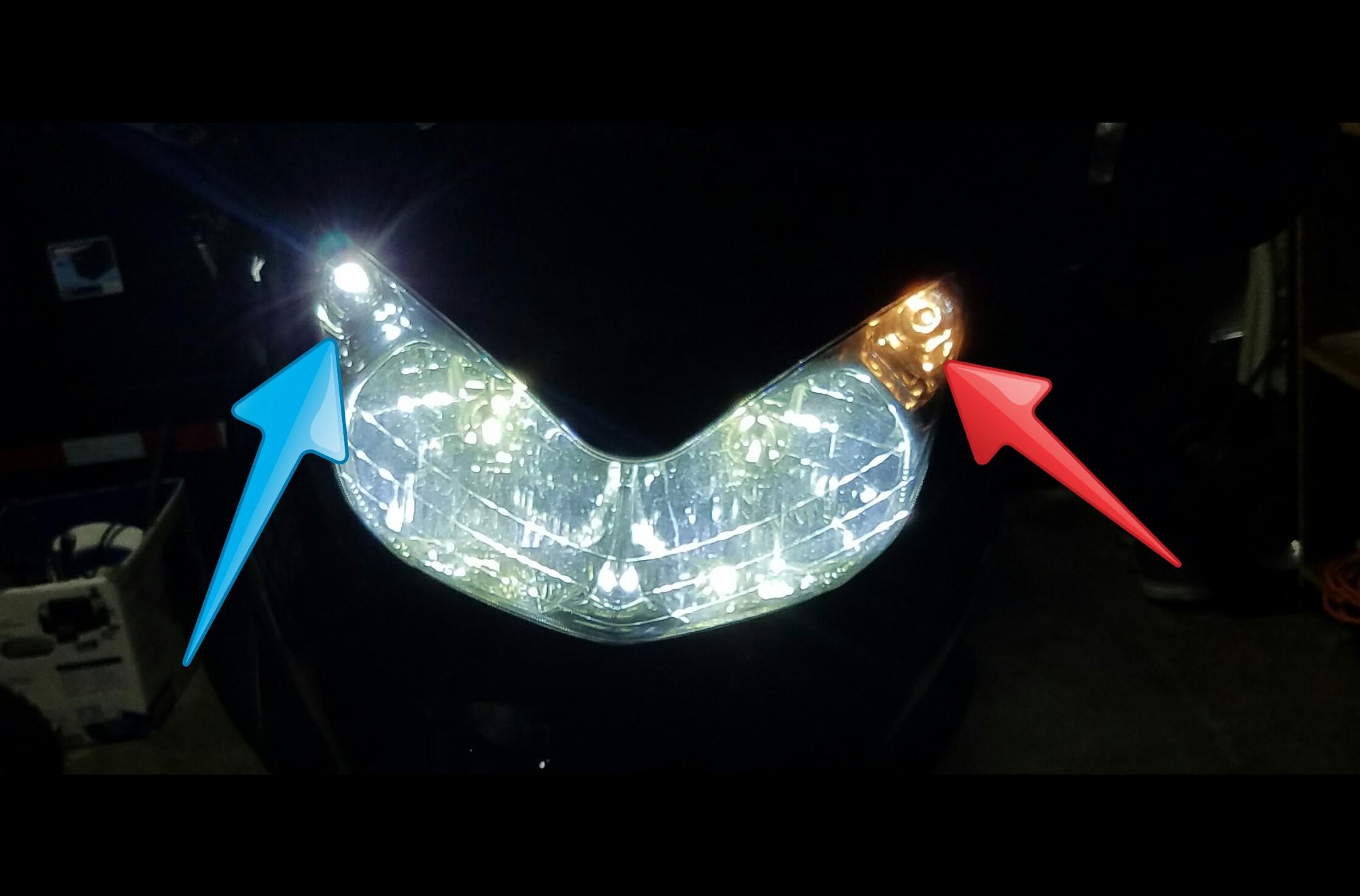
POSITION LIGHT REPLACEMENT
Next we will replace the position lights, or park lights, or marker lights. The little guys in the top corner (see images).
Locate the bulb socket. You will find a small rubber boot at the end of the wiring harness (see image). Pull this rubber socket straight out, but use caution! There is nothing really "locking" the bulb on so as you pull, the bulb may dislodge from the rubber socket and fall into the housing.
Once you have the socket removed simply pull the old bulb out, and plug in the new LED.
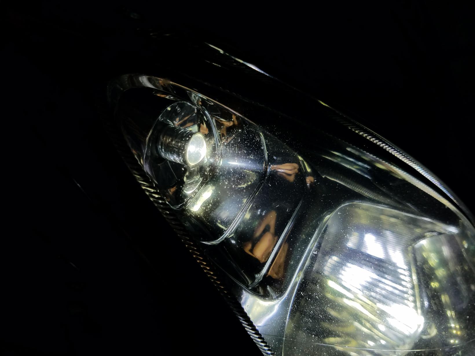
ALL DONE!!!! Now get out and ride! Stay safe!
~~~
Thank You again for your contribution aka JayBear, STOC #XXXX
Original posting link: www.st-owners.com
~~~
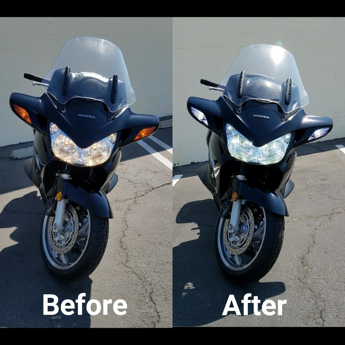
LED Headlight Conversion ( ST1300 )
How many ST riders does it take to change a light bulb[emoji47]
Hello fellow ST riders!
If you're trying to figure out how to install your new LED headlights then you have come to the right place. I recently changed out the lighting on the front of my ST1300 to all LEDs and realized information on the process was scattered all over so I decided to document my entire process by taking photos along the way. My hope is that this guide will help you to visualize the process and help you understand the mechanisms involved so that you can spend less time fumbling around and looking all over the threads for info.
Disclaimer: I am not a mechanic, electrical engineer, or a rocket scientist (go figure)! I am just an average DIY-er so use this information accordingly. Enough chit-chat, let's get to it!
BACKGROUND INFO AND SPECS
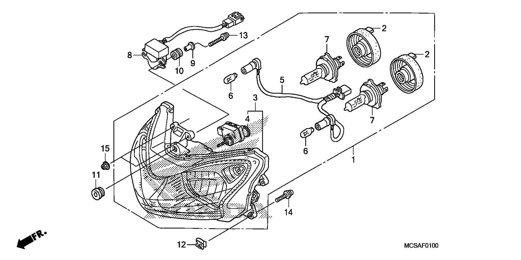
- Bike: 2006 Honda ST1300 (non abs) USA
- OEM Headlight: H4/9003/HB2 12v, 45/45 Watt
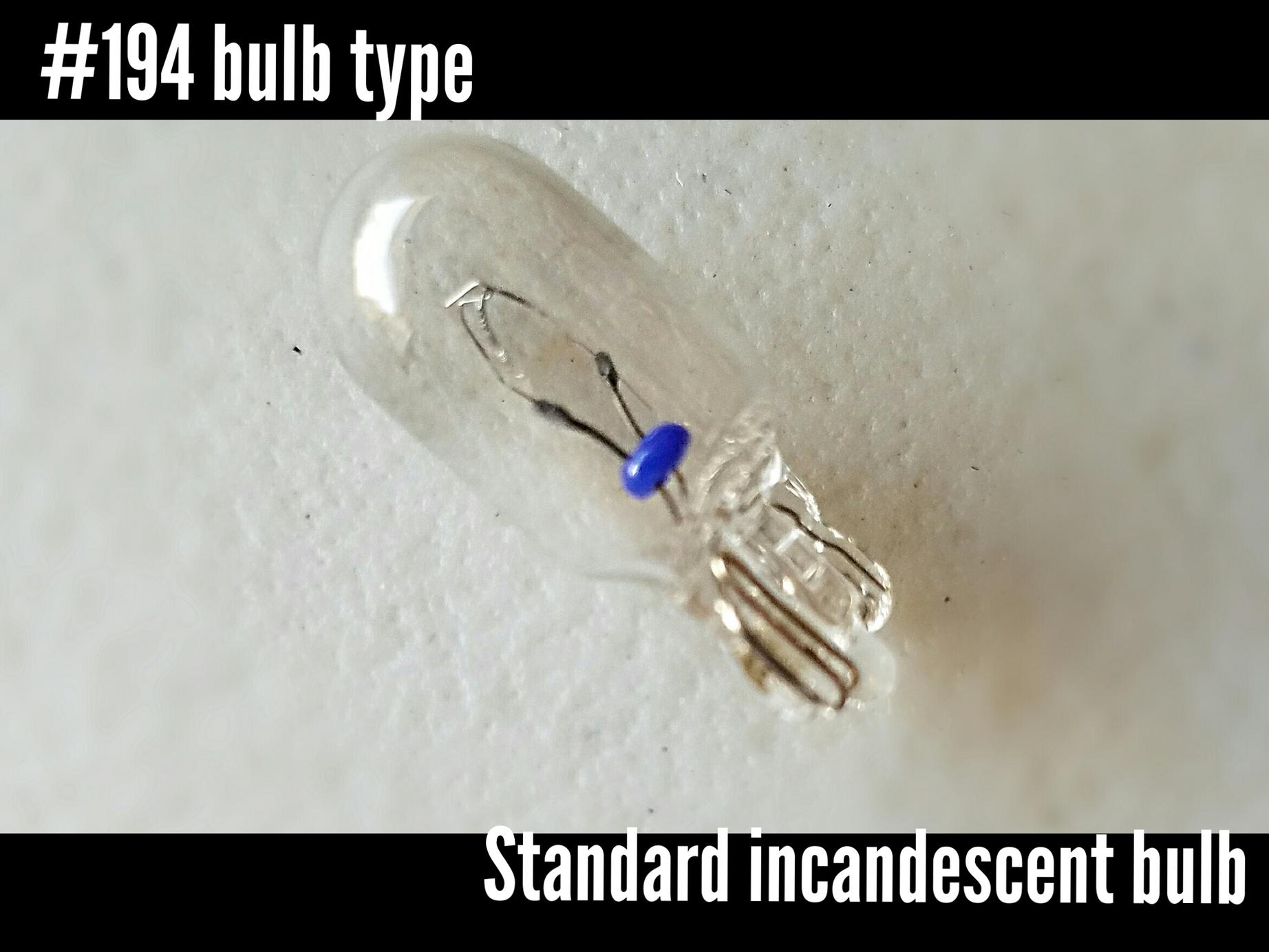
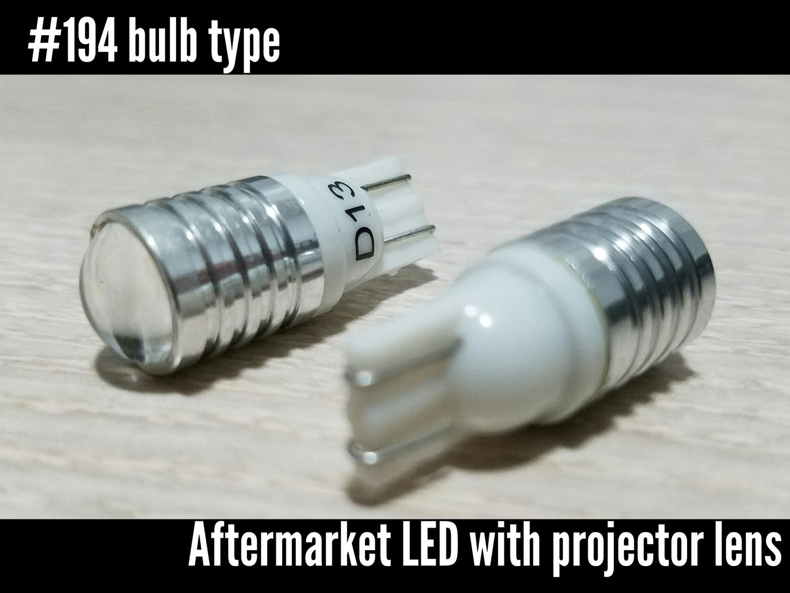
- OEM Position Light: 194/T10, 12v, 5 watt
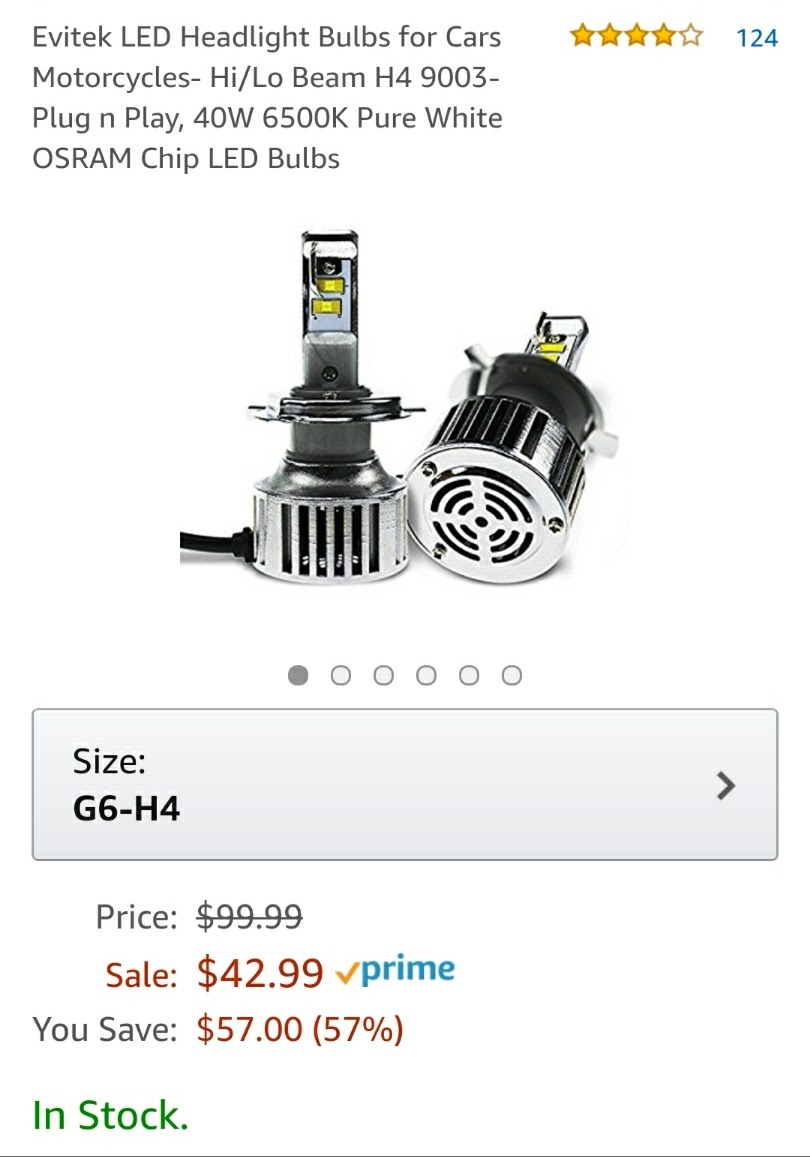
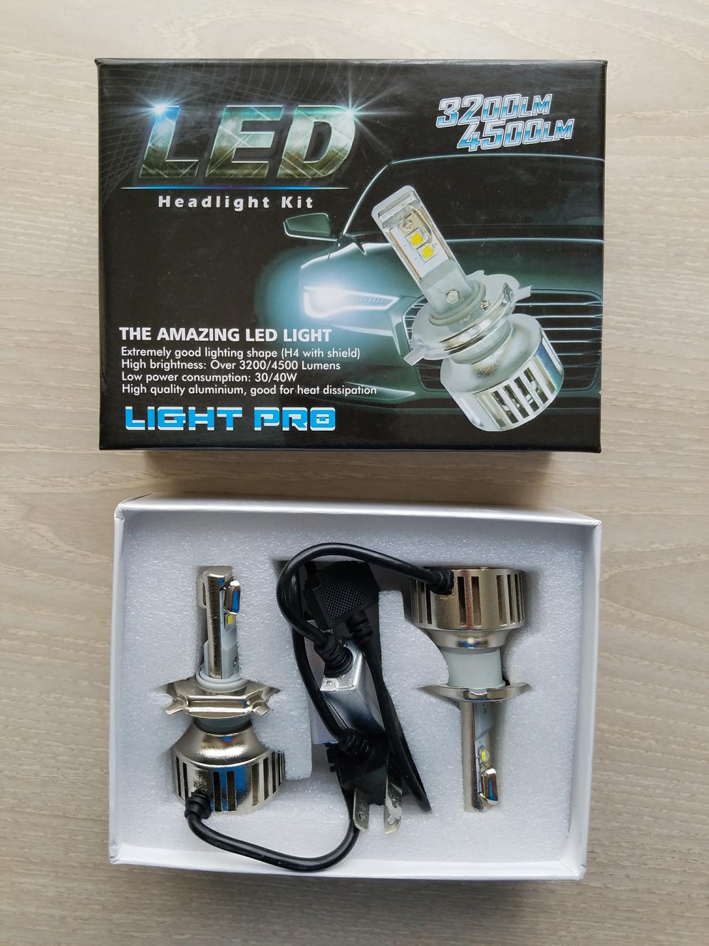
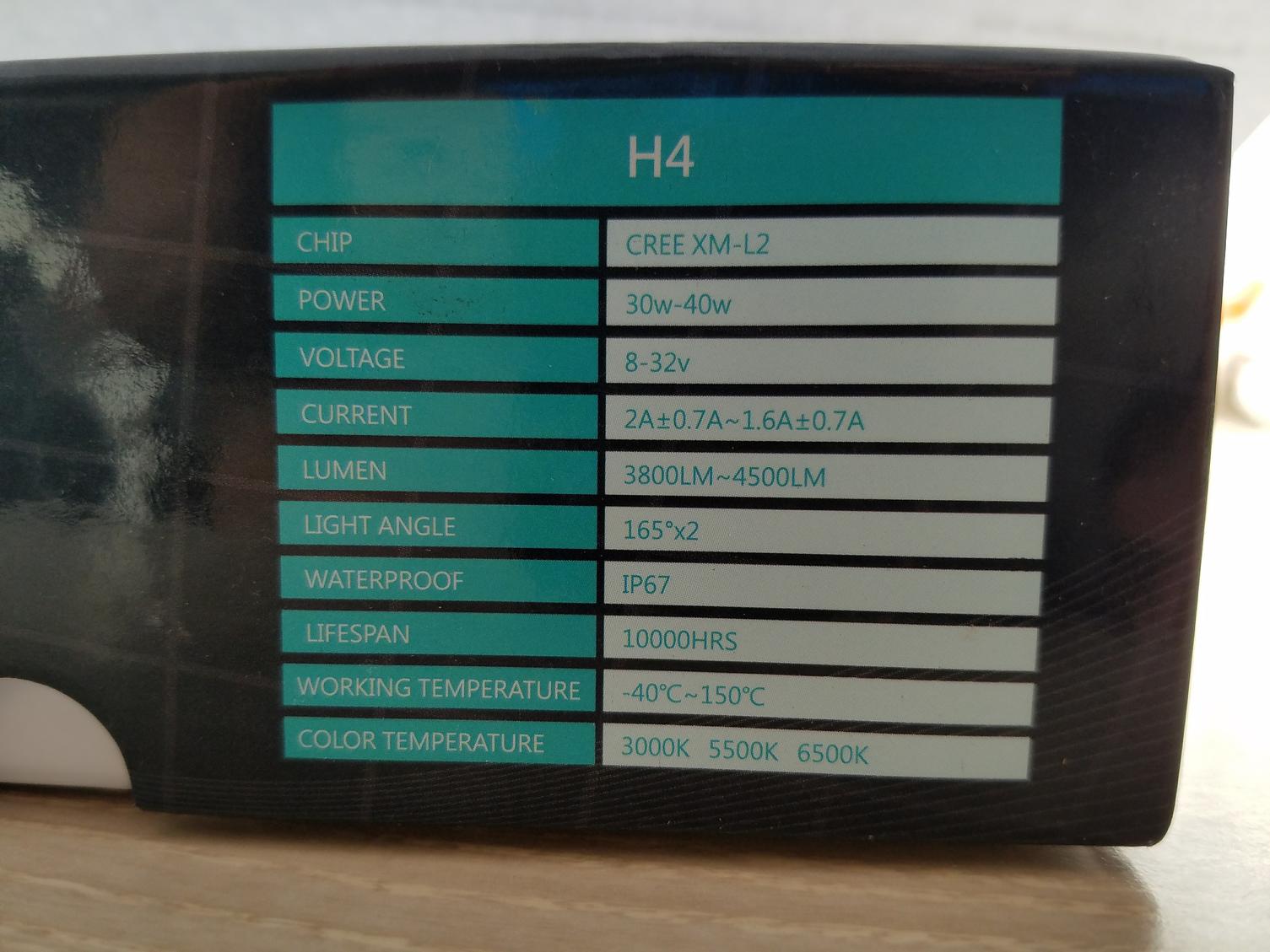
- LED Replacement Headlight: Evitek G6 H4 type, 40 watt 6500k pure white OSRAM chip LED Bulbs
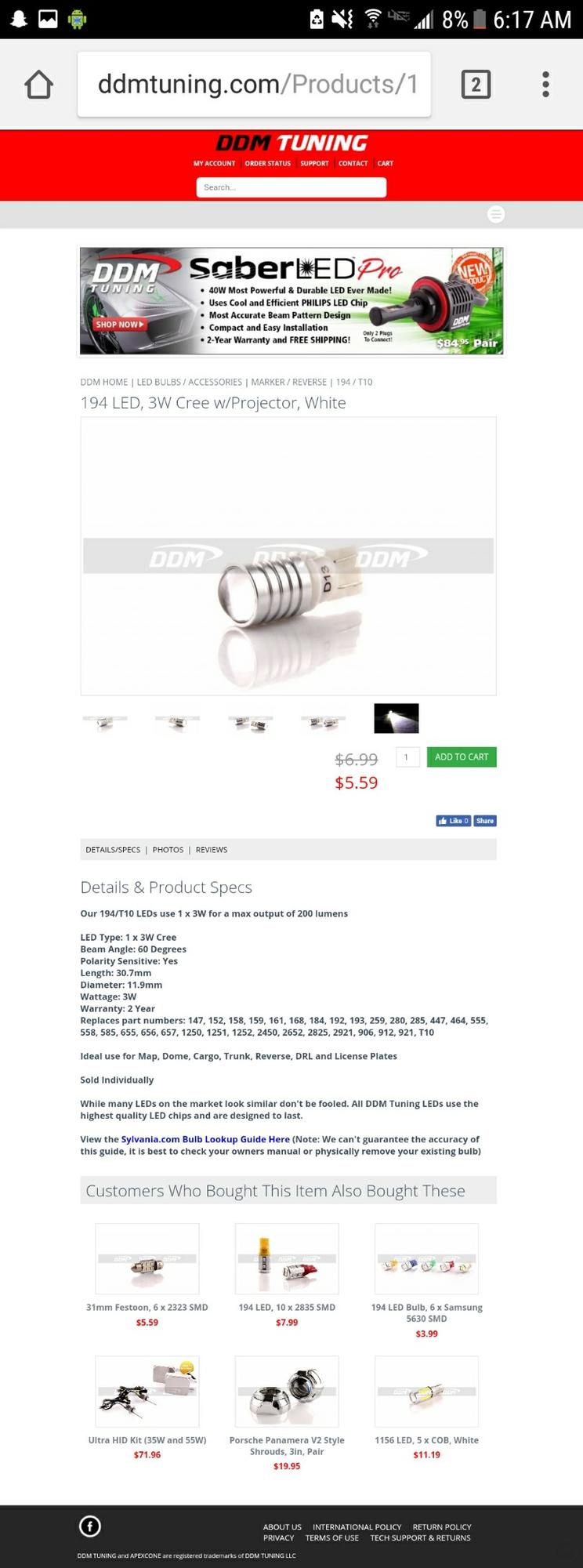
- LED Replacement Position Light: DDM Tuning 194 LED, 3W Cree w/Projector Lens (White)
It is important to note that the tabs on the OEM bulb and the notches on the OEM housing do not have the same angle as an aftermarket H4 bulb (see photo below for comparison).
Notice the bottom two tabs on the OEM bulb are more spread out. Because of this you will need to modify the new bulb.
Common solutions are
- Cut the tabs off
- Bend the tabs back, or
- Use shims
***SIDE NOTE***
WHAT ARE SHIMS? They are metal rings cut to match the OEM tab angle. You just slip them on over the bulb so that you can lock them in place. Although not required for this project I want to share the info here.
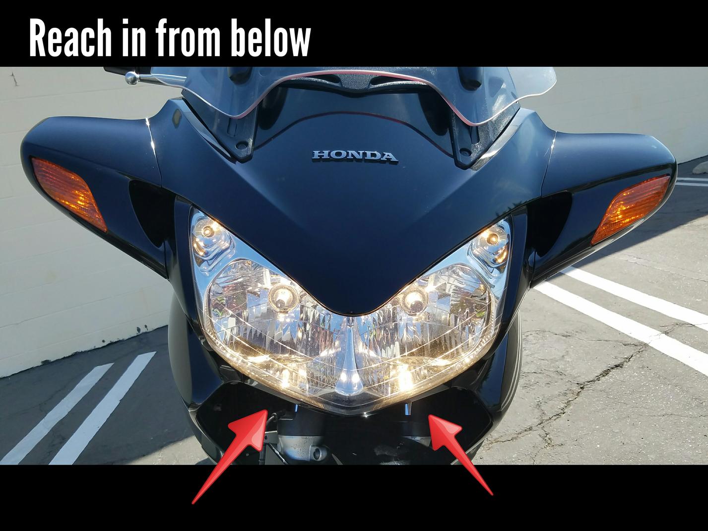
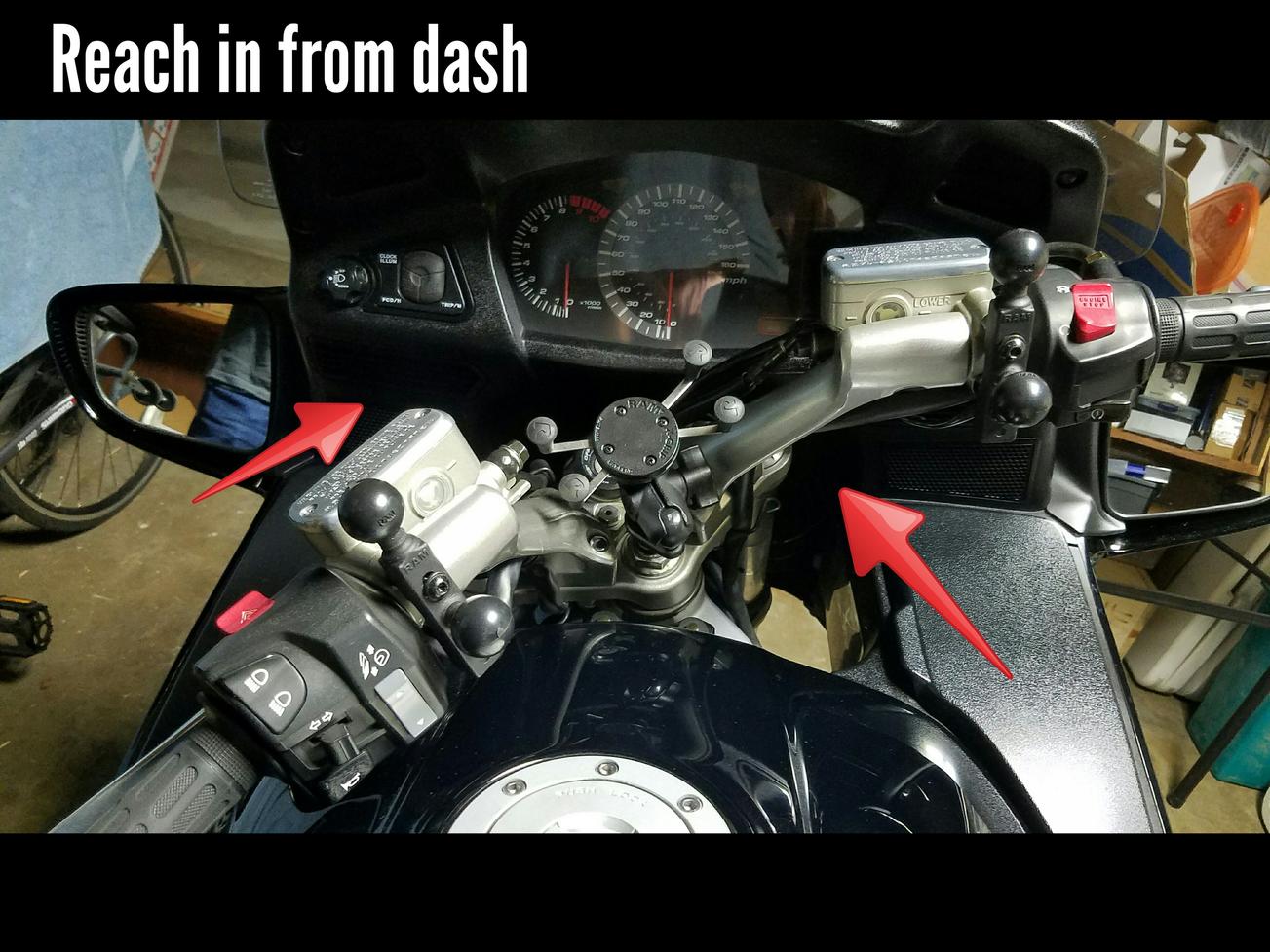
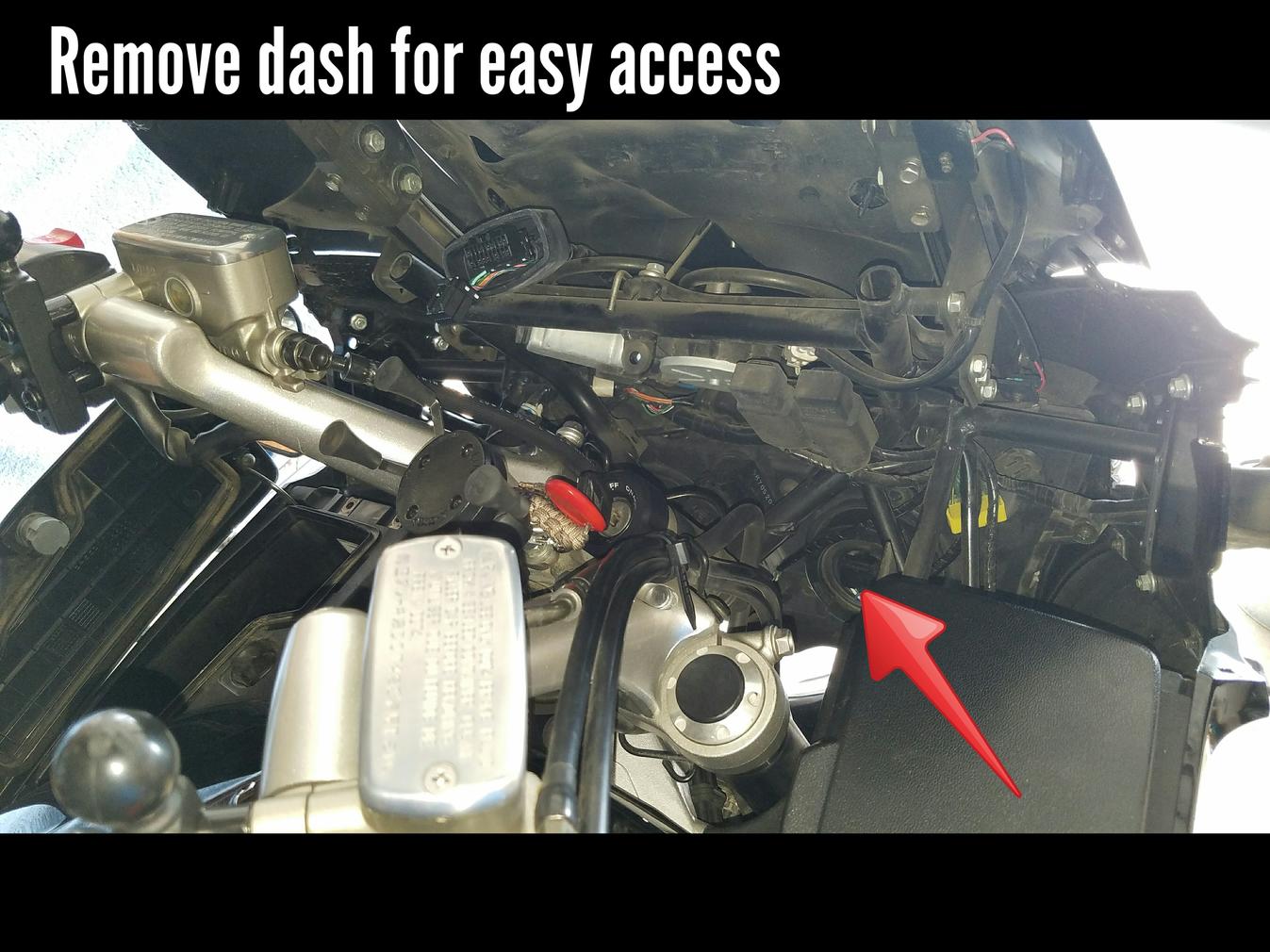
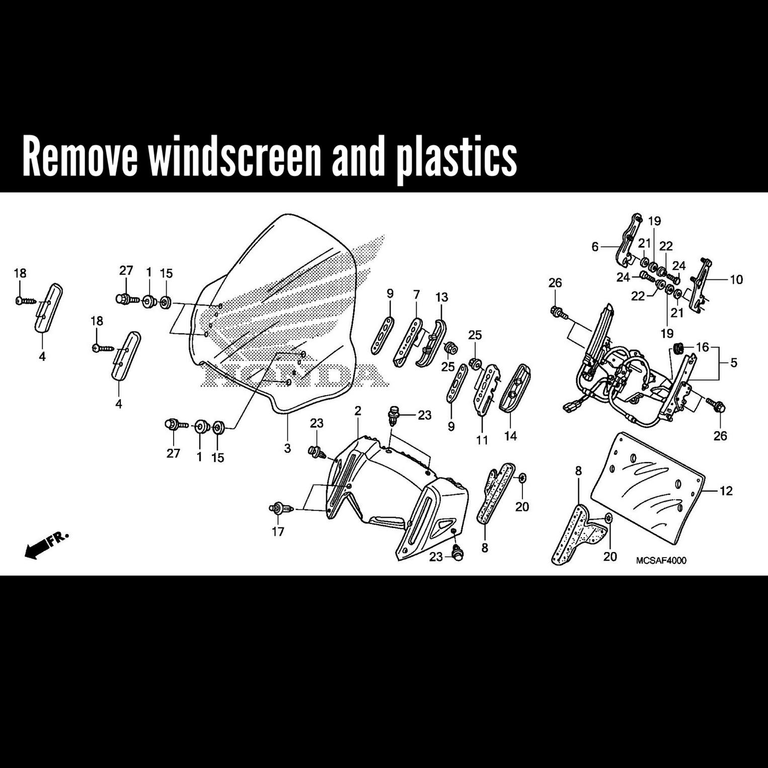
Next item is how to access the bulbs. I used option #3 but other common solutions are (see images)
- Reach in from from the front of the bike and below the headlight housing
- Reach in from above behind the handlebars
- Remove the dash/instrument panel
- Remove the front windscreen and surrounding plastics
- Remove side fairings
HEADLIGHT REPLACEMENT
Locate the headlight. You will see a big round rubber boot with an electrical connector in the middle. You need to remove this connector. To do this you need to press down on the tabs located on either side of the connector (see image). You may need to dig your fingers into the boot a little bit to reach these tabs. You are disconnecting the harness from the bulb so you should only have to pull straight out but some wiggling may be required.
Once you have the connector from the wiring harness out, remove the rubber boot. Just grab from the edges and pull/peel back.
When the boot is off it will reveal the wire clip and the bulb. Now unlatch the wire clip, or bail clip, by pushing in with your thumb and turning slightly. The clip will unhook and swing open to free the bulb from the housing.
Then remove the bulb. Just pull straight out. Be careful not to let your fingers touch the glass if you plan on keeping the bulbs. If you do accidentally touch the glass then use a small amount of rubbing alcohol to clean it.
Now before you insert the new LED bulb you will need to modify it as mentioned earlier. Choose your weapon. I used a Dremel with a metal cutting wheel bit to cut and file off the lower two tabs.
You need to know that the mounting plate (blue arrow, see image) that has the three tabs is removable. Just hold the plate with one hand the the fan with your other hand and twist. That will release the plate.
Now take the mounting plate (blue arrow, see image) and insert into the headlight housing by itself. Do not attach it to the bulb or else it will not fit! It will all make sense later. You must align the top tab with the notch in the housing (see image).
When you have the mounting plate inserted re-insert the wire clip to hold it down. This might take a while
Now that the clip is back in put the rubber boot back on. Still no bulb should be inserted! I have seen posts where people leave the rubber boot off or even cut it up to make the hole wider but this is not required.
Okay, now you can insert the LED bulb in through the rubber boot. Remember those notches on the bulb from when you removed the mounting plate? Well you need to align them so that you can insert the bulb and then twist to lock it back in place. It will help to look through the front of the housing when you insert the bulb. Look for the notch to help you with the alignment (blue arrow, see image).
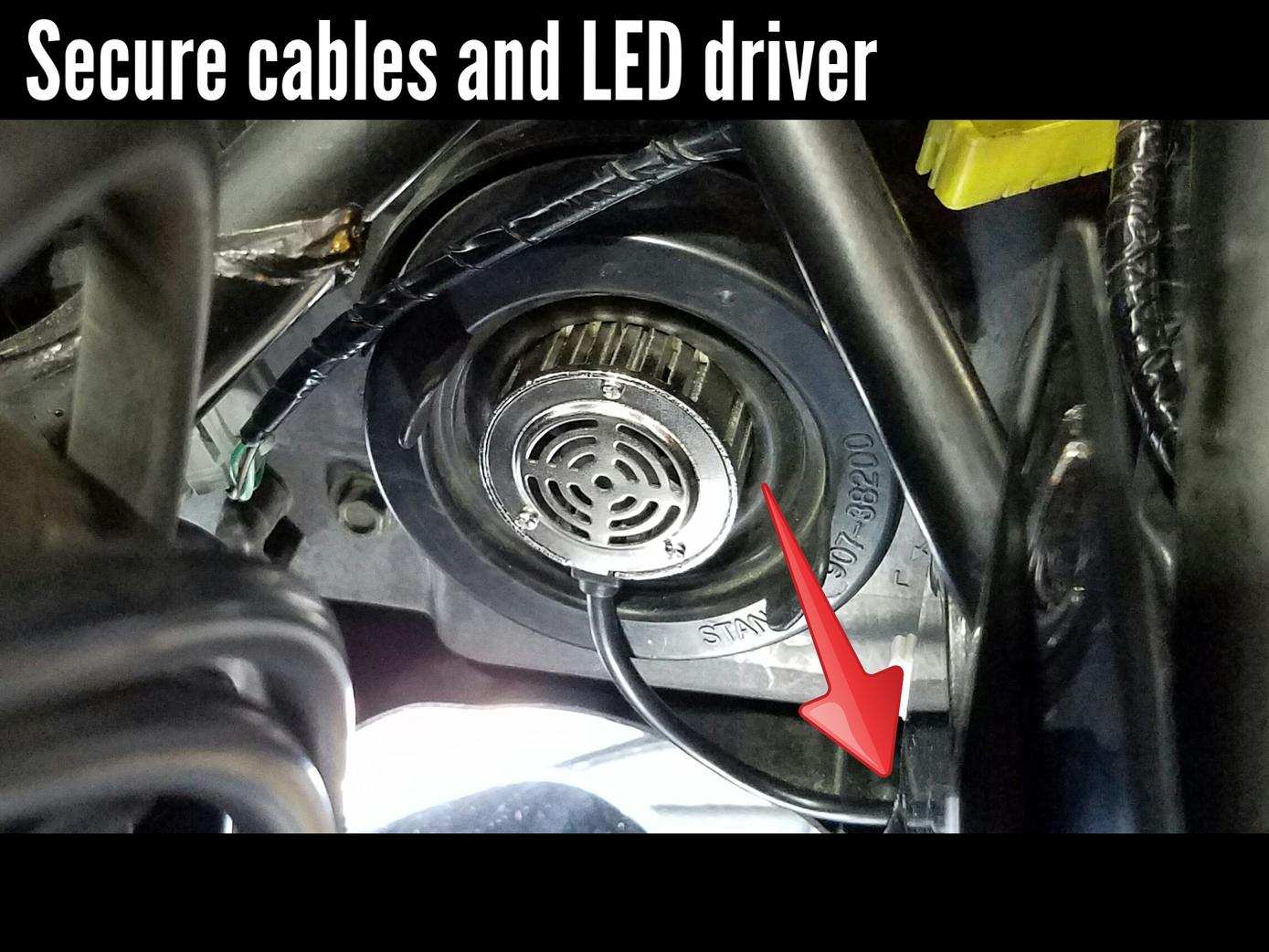
After you have the bulb locked in you're almost done. Just plug the electrical connector to the new bulb and tuck away and zip-tie the wires and the LED driver (ballast/box thing). I tied them off to the side so that it would not interfere when turning the handle bars.
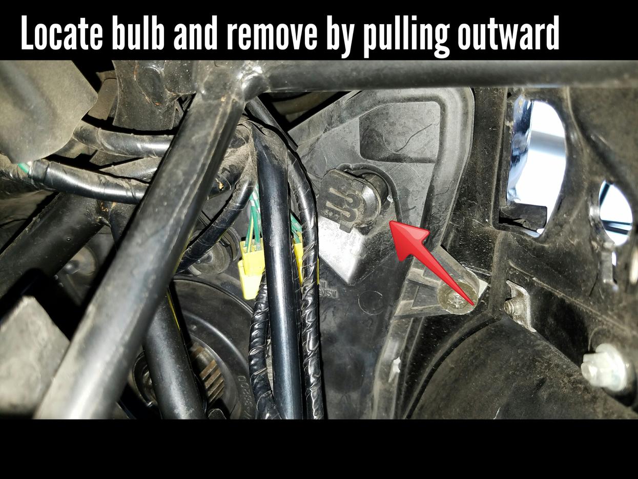
POSITION LIGHT REPLACEMENT
Next we will replace the position lights, or park lights, or marker lights. The little guys in the top corner (see images).
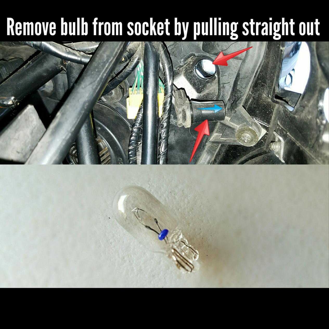
Locate the bulb socket. You will find a small rubber boot at the end of the wiring harness (see image). Pull this rubber socket straight out, but use caution! There is nothing really "locking" the bulb on so as you pull, the bulb may dislodge from the rubber socket and fall into the housing.
Once you have the socket removed simply pull the old bulb out, and plug in the new LED.
ALL DONE!!!! Now get out and ride! Stay safe!
~~~
Thank You again for your contribution aka JayBear, STOC #XXXX
#16
ST1100 Archive of Wisdom / Brakes - Operation of the Mast...
Last post by KoTAOW - January 09, 2018, 12:43:19 PM* * * Article pending permission by Author * * *
Submitted by John Heath, STOC #XXXX
Original article can be found here:
www.st-owners.com
~~~
Brakes - Operation of the Master Cylinder ( ST1100\ST1300 )
Some basic information here about the operation of the brake master cylinder.
This document was last edited on 17 July 2017 to remove references to 'relief port' and use the more correct 'compensating port'.
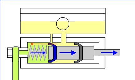
1 - 'Relaxed' Brake Master Cylinder (ie Brakes are not Applied)
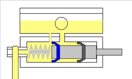
The image shows the front master cylinder and the reservoir immediately above it - just like the ones used on the clutch and brake lever on the ST1300. The piston and push rod are shown in grey.
The primary seal (blue) is the one that applies considerable pressure to the braking system.
The secondary seal (black) maintains a body of fluid behind the primary seal which is gravity fed from the reservoir above. It also isolates the system from the outside world. This seal is never normally put under any great (ie braking force) pressure. The ST1300s secondary master cylinder being an exception to this arrangement.
Note the larger inlet port between the reservoir and the piston/cylinder. This maintains a volume of fluid between the two seals, fed constantly from the reservoir. The inlet port is never closed off by the position of the piston and seals.
The tiny compensating port is immediately in front (just to the left) of the primary seal. This allows fluid in the braking system to return into the reservoir and relieves any build up of pressure when the braking system is in this 'relaxed' state.
The spring is responsible for returning the piston to the right on this diagram. The push rod at the right hand end is operated by the brake lever.
The hose to the brake calliper is shown descending beyond the bottom of the picture on the left of the master cylinder.
----------------------------------------------------------------------
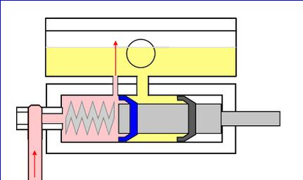
2 - Master Cylinder when Brake is Applied
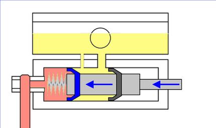
In Diagram 2, the piston has been pushed to the left. Fluid under pressure (pink) is forced down the brake line to the pistons in the brake caliper. Note that the primary seal (blue) has moved past the compensating port, preventing any fluid from returning to the reservoir. The fluid under pressure is responsible for pushing out the pistons in the brake calliper which push the brake pads onto the disc rotors. Once the brake pads are in contact with the disc rotors it takes only a small movement in the master cylinder (brake lever) to exert a force sufficient to bring the bike to a halt.
----------------------------------------------------------------------
3 - Releasing the Brake Lever
When the brake lever is released, the piston and plunger are returned to the initial 'relaxed' position primarily as a result of the spring pressure in the master cylinder, but aided by the flexible hoses and the calliper piston seals returning to their normal state.
Each time the brakes are applied, the pads wear down a tiny fraction, and the calliper pistons are pushed out further than they were before the brakes were applied. When the brakes are released, the spring returns the master cylinder piston to its relaxed state and a negative pressure (vacuum) is created in the brake lines. Fluid is able to flow past the lips of the primary seal to allow for the fact that the pads have worn down a little.
The diagram shows the piston towards the end of its travel back to its 'relaxed' state, and the red arrow indicates the flow of extra fluid from the yellow reservoir fluid and into the brake lines (green fluid).
----------------------------------------------------------------------
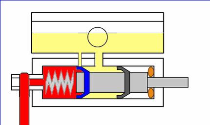
4 - Dealing with Pressure Build-up
When the brake is not being applied, and the system is in a relaxed state, it is important that fluid is able to 'flow' to and from the reservoir as required. This is can happen when:-
* A slight warps in the disc rotors or general chattering of the brakes over bumpy surfaces pushes the pistons in slightly.
* An increases in temperature causes the fluid to expand.
* The bike cools down in the garage overnight and the fluid contracts. The relief port allows fluid to flow into the brake lines rather than suck the calliper pistons back.
* The brake pads are replaced and the calliper pistons are pushed in. The displaced fluid returns to the reservoir through the tiny relief port. No damage can result in pushing in the calliper pistons in this way if the system has been flushed with new fluid and the exposed calliper pistons are clean. Otherwise it is better to expel the old fluid from the calliper bores via the bleed valve.
The picture shows the pressure in the brake line being allowed to pass through the tiny compensating port into the reservoir, once the brake lever has been released. To prevent the 'fountain' shown in the diagram, a small chromed disc clips slightly above the port at the bottom of the reservoir.
----------------------------------------------------------------------
5 - Blocked Pressure Relief Port
If the piston is prevented from returning to its proper 'relaxed' state, then the Primary Seal will not expose the tiny compensating port. This could be caused by corrosion behind the piston, as shown. This part of the piston is open to the elements unless treated with silicone grease and covered with a rubber boot.
Alternatively, the compensating port itself could be blocked. Fluid that isn't replaced every year can turn into a thick gel which accumulates in the bottom of the reservoir. Or perhaps debris has fallen into the reservoir during a service.
Whatever, if the compensating port is not clear, or the piston fails to return properly to expose the compensating port, pressure builds up (red) and the brakes lock on solid. I have seen one situation recently where a master cylinder service kit was supplied incorrectly. The push rod was slightly too long and front brakes locked on solid at the first application and would not release.
----------------------------------------------------------------------
The illustrations refer to the ST1300 front master cylinder, but the principles also apply to the secondary master cylinder and the rear master cylinder, even though their relief port is connected to the fluid inlet line rather than to the reservoir itself.
-----------------------------------------------------------------------
Final note. Throughout this document, I have made much more of the role of the compensating port in relieving pressure than its other functions.
In fact, the port will allow fluid to flow in either direction to add or remove fluid from the lines to compensate for the fact that the existing fluid will expand or contract as the temperature fluctuates. To do this, the master cylinder piston has to be returned to its relaxed position so that the port is not blocked by the seal. The spring in the master cylinder ensures that this happens.
~~~
Thank You again for your contribution John Heath, STOC #XXXX
#17
ST1300 Archive of Wisdom / Brakes - Operation of the Mast...
Last post by KoTAOW - January 09, 2018, 12:41:45 PMSubmitted by John Heath, STOC #2570
Original article can be found here:
www.st-owners.com
~~~
Brakes - Operation of the Master Cylinder ( ST1100\ST1300 )
Some basic information here about the operation of the brake master cylinder.
This document was last edited on 17 July 2017 to remove references to 'relief port' and use the more correct 'compensating port'.
1 - 'Relaxed' Brake Master Cylinder (ie Brakes are not Applied)
The image shows the front master cylinder and the reservoir immediately above it - just like the ones used on the clutch and brake lever on the ST1300. The piston and push rod are shown in grey.
The primary seal (blue) is the one that applies considerable pressure to the braking system.
The secondary seal (black) maintains a body of fluid behind the primary seal which is gravity fed from the reservoir above. It also isolates the system from the outside world. This seal is never normally put under any great (ie braking force) pressure. The ST1300s secondary master cylinder being an exception to this arrangement.
Note the larger inlet port between the reservoir and the piston/cylinder. This maintains a volume of fluid between the two seals, fed constantly from the reservoir. The inlet port is never closed off by the position of the piston and seals.
The tiny compensating port is immediately in front (just to the left) of the primary seal. This allows fluid in the braking system to return into the reservoir and relieves any build up of pressure when the braking system is in this 'relaxed' state.
The spring is responsible for returning the piston to the right on this diagram. The push rod at the right hand end is operated by the brake lever.
The hose to the brake calliper is shown descending beyond the bottom of the picture on the left of the master cylinder.
----------------------------------------------------------------------
2 - Master Cylinder when Brake is Applied
In Diagram 2, the piston has been pushed to the left. Fluid under pressure (pink) is forced down the brake line to the pistons in the brake caliper. Note that the primary seal (blue) has moved past the compensating port, preventing any fluid from returning to the reservoir. The fluid under pressure is responsible for pushing out the pistons in the brake calliper which push the brake pads onto the disc rotors. Once the brake pads are in contact with the disc rotors it takes only a small movement in the master cylinder (brake lever) to exert a force sufficient to bring the bike to a halt.
----------------------------------------------------------------------
3 - Releasing the Brake Lever
When the brake lever is released, the piston and plunger are returned to the initial 'relaxed' position primarily as a result of the spring pressure in the master cylinder, but aided by the flexible hoses and the calliper piston seals returning to their normal state.
Each time the brakes are applied, the pads wear down a tiny fraction, and the calliper pistons are pushed out further than they were before the brakes were applied. When the brakes are released, the spring returns the master cylinder piston to its relaxed state and a negative pressure (vacuum) is created in the brake lines. Fluid is able to flow past the lips of the primary seal to allow for the fact that the pads have worn down a little.
The diagram shows the piston towards the end of its travel back to its 'relaxed' state, and the red arrow indicates the flow of extra fluid from the yellow reservoir fluid and into the brake lines (green fluid).
----------------------------------------------------------------------
4 - Dealing with Pressure Build-up
When the brake is not being applied, and the system is in a relaxed state, it is important that fluid is able to 'flow' to and from the reservoir as required. This is can happen when:-
* A slight warps in the disc rotors or general chattering of the brakes over bumpy surfaces pushes the pistons in slightly.
* An increases in temperature causes the fluid to expand.
* The bike cools down in the garage overnight and the fluid contracts. The relief port allows fluid to flow into the brake lines rather than suck the calliper pistons back.
* The brake pads are replaced and the calliper pistons are pushed in. The displaced fluid returns to the reservoir through the tiny relief port. No damage can result in pushing in the calliper pistons in this way if the system has been flushed with new fluid and the exposed calliper pistons are clean. Otherwise it is better to expel the old fluid from the calliper bores via the bleed valve.
The picture shows the pressure in the brake line being allowed to pass through the tiny compensating port into the reservoir, once the brake lever has been released. To prevent the 'fountain' shown in the diagram, a small chromed disc clips slightly above the port at the bottom of the reservoir.
----------------------------------------------------------------------
5 - Blocked Pressure Relief Port
If the piston is prevented from returning to its proper 'relaxed' state, then the Primary Seal will not expose the tiny compensating port. This could be caused by corrosion behind the piston, as shown. This part of the piston is open to the elements unless treated with silicone grease and covered with a rubber boot.
Alternatively, the compensating port itself could be blocked. Fluid that isn't replaced every year can turn into a thick gel which accumulates in the bottom of the reservoir. Or perhaps debris has fallen into the reservoir during a service.
Whatever, if the compensating port is not clear, or the piston fails to return properly to expose the compensating port, pressure builds up (red) and the brakes lock on solid. I have seen one situation recently where a master cylinder service kit was supplied incorrectly. The push rod was slightly too long and front brakes locked on solid at the first application and would not release.
----------------------------------------------------------------------
The illustrations refer to the ST1300 front master cylinder, but the principles also apply to the secondary master cylinder and the rear master cylinder, even though their relief port is connected to the fluid inlet line rather than to the reservoir itself.
-----------------------------------------------------------------------
Final note. Throughout this document, I have made much more of the role of the compensating port in relieving pressure than its other functions.
In fact, the port will allow fluid to flow in either direction to add or remove fluid from the lines to compensate for the fact that the existing fluid will expand or contract as the temperature fluctuates. To do this, the master cylinder piston has to be returned to its relaxed position so that the port is not blocked by the seal. The spring in the master cylinder ensures that this happens.
~~~
Thank You again for your contribution John Heath, STOC #2570
#18
ST1300 Archive of Wisdom / Linked vs. Non-Linked Brake S...
Last post by KoTAOW - December 04, 2017, 06:23:16 PMSubmitted by David Helck, aka Anna's Dad
Original posting link: www.st-owners.com
~~~
The Dual Combined Brake System (DCBS) that Honda employed for the ST1300 is an effective, marvelous, and complex example of hydraulic/mechanical design. Unfortunately due to a dearth of easily accessible information for this design, a comprehensive understanding of the operation of the DCBS has remained elusive.
However this is changing, with the availability of low cost DCBS components on eBay, I have purchased, disassembled, measured, and drawn most (if not all) of the brake components for the Honda ST1300. With each component now carefully documented, it became an interesting task to try and puzzle out (reverse engineer) what the original designers were trying to accomplish.
Below are the links to the various brake components that I have documented, please note that the descriptions of operation with each component (probably on the order of 90% correct) are based on my interpretations of the hydraulic/mechanical design.
Linked Brake System (pdf)
This drawing is a general over view of the DCBS as used on the Honda ST1300.
Direct link: https://drive.google.com/file/d/0B5AgdjJdxahQajJVNFJDdzZXRVk/
Components of Honda DCBS (pdf)
This drawing is again an over view of the DCBS with a focus on the individual brake components, and how they interact with one another.
Direct link: https://drive.google.com/file/d/0B5AgdjJdxahQUUNUTDVSRHhxX0E/
Secondary Master Cylinder (pdf)
This drawing is a detailed explanation of the SMC as used on the Honda ST1300.
Direct link: https://drive.google.com/file/d/0B5AgdjJdxahQUUJISU40ZjZyMGc/
SMC Stages of Operation (pdf)
This drawing attempts to demonstrate the operation of the SMC showing fluid flow during operation.
Direct link: https://drive.google.com/file/d/0B5AgdjJdxahQX2Z3SU9pQU1iQnc/
Brake - Delay Valve (pdf)
This drawing is an explanation of the Delay Valve, demonstrating the operation of the Delay Valve showing fluid flow during operation.
Direct link: https://drive.google.com/file/d/0B5AgdjJdxahQWHNqbXFIX2hjbkE/
Brake - Proportioning Valve (pdf)
This drawing is an explanation of the Proportional Valve, demonstrating the operation of the Proportional Valve showing fluid flow during operation.
Direct link: https://drive.google.com/file/d/0B5AgdjJdxahQalhNcVJJQnhuT2M/
Lastly, here's a link to more motorcycle drawings.
These are drawings that I've made relating to either my '06 Honda ST1300/A, or my daughter's '07 Kawasaki 250R.
Direct link: https://docs.google.com/document/d/1w__nEUkBfthrr5oP7o7Te7lCeZz7Zijk44ZDyFZ65RM/mobilebasic?authkey=CI_Zq2E&hl=en&pli=1#
My goal in this undertaking is to provide a resource for other curious Honda (and non Honda) motorcycle owners who just "want to know".
Cheers.
~~~
Thank You again for your contribution David Helck, aka Anna's Dad
Original posting link: www.st-owners.com
~~~
Linked vs. Non-Linked Brake Schematics
( ST1300 )
The Dual Combined Brake System (DCBS) that Honda employed for the ST1300 is an effective, marvelous, and complex example of hydraulic/mechanical design. Unfortunately due to a dearth of easily accessible information for this design, a comprehensive understanding of the operation of the DCBS has remained elusive.
However this is changing, with the availability of low cost DCBS components on eBay, I have purchased, disassembled, measured, and drawn most (if not all) of the brake components for the Honda ST1300. With each component now carefully documented, it became an interesting task to try and puzzle out (reverse engineer) what the original designers were trying to accomplish.
Below are the links to the various brake components that I have documented, please note that the descriptions of operation with each component (probably on the order of 90% correct) are based on my interpretations of the hydraulic/mechanical design.
Linked Brake System (pdf)
This drawing is a general over view of the DCBS as used on the Honda ST1300.
Direct link: https://drive.google.com/file/d/0B5AgdjJdxahQajJVNFJDdzZXRVk/
Components of Honda DCBS (pdf)
This drawing is again an over view of the DCBS with a focus on the individual brake components, and how they interact with one another.
Direct link: https://drive.google.com/file/d/0B5AgdjJdxahQUUNUTDVSRHhxX0E/
Secondary Master Cylinder (pdf)
This drawing is a detailed explanation of the SMC as used on the Honda ST1300.
Direct link: https://drive.google.com/file/d/0B5AgdjJdxahQUUJISU40ZjZyMGc/
SMC Stages of Operation (pdf)
This drawing attempts to demonstrate the operation of the SMC showing fluid flow during operation.
Direct link: https://drive.google.com/file/d/0B5AgdjJdxahQX2Z3SU9pQU1iQnc/
Brake - Delay Valve (pdf)
This drawing is an explanation of the Delay Valve, demonstrating the operation of the Delay Valve showing fluid flow during operation.
Direct link: https://drive.google.com/file/d/0B5AgdjJdxahQWHNqbXFIX2hjbkE/
Brake - Proportioning Valve (pdf)
This drawing is an explanation of the Proportional Valve, demonstrating the operation of the Proportional Valve showing fluid flow during operation.
Direct link: https://drive.google.com/file/d/0B5AgdjJdxahQalhNcVJJQnhuT2M/
Lastly, here's a link to more motorcycle drawings.
These are drawings that I've made relating to either my '06 Honda ST1300/A, or my daughter's '07 Kawasaki 250R.
Direct link: https://docs.google.com/document/d/1w__nEUkBfthrr5oP7o7Te7lCeZz7Zijk44ZDyFZ65RM/mobilebasic?authkey=CI_Zq2E&hl=en&pli=1#
My goal in this undertaking is to provide a resource for other curious Honda (and non Honda) motorcycle owners who just "want to know".
Cheers.
~~~
Thank You again for your contribution David Helck, aka Anna's Dad
#19
ST1100 Archive of Wisdom / Re: Third Tail or Additional B...
Last post by KoTAOW - November 16, 2017, 11:27:46 AMSubmitted by Norm Keller, STOC#8030
~~~
I added an H1 quartz bulb linked through a relay and load type flasher to the rear brake light wire.
It is a bit brighter than the other two (side) original brake lights but not enough to draw "official" disapproval. When the brake is applied, the three bulbs light and after about two seconds, the load type signal flasher begins to cycle which creates a very eye catching effect. I used an old KLR650 signal flasher because I wanted a delay before the flashing begins and an electronic or heavier load type begins to flash immediately.
Easy to do and, IMO, well worth the time required.
I seem not to be able to find photos of the bulb install but someone else posted these so they will be found.
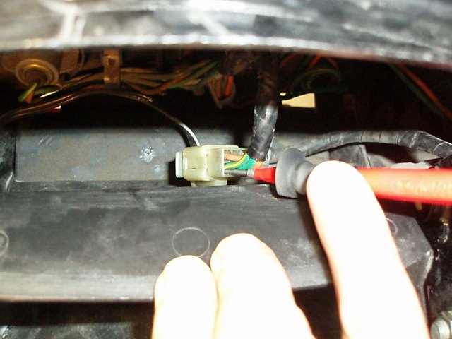
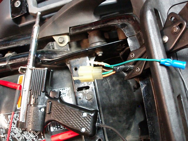
Identify the brake light wire in the rear plug behind the under seat storage panel.
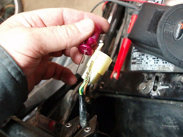
Remove the brake light terminal from the junction plug. Note that I do not like to cut into wiring and prefer to add the lead to the original plug in such a way that the system can be returned to stock if desired. The special tool is used to push the little latch lever in to allow the terminal to be withdrawn from the body of the plug. Bend the lever out again before sliding the terminal back into place.
Solder the lead wire to the terminal, positioned to allow the terminal to be replaced into the plug body. The other end of the lead wire has a female bullet connector to allow the third bulb harness to be connected or removed for service. By the way; if you are in the market for a solder gun for shop use, get one of these Wall LG400C units. Mac Tools sell them as do other sources. They are so superior to the transformer type made by Weller and such as to beggar comparison. The weight is a fraction and much more compact. 400 Watt output heats up in a few seconds and has enough go for heavy terminals. If that's not enough, get the 550 Watt element. I've seen them advertised for around $60 yes, I own one, and yes, I used to sell them. The other types are crap! As any alternator repair shop!
Power for the relay was taken from the fuse box and is live because the circuit is controlled by the brake light switch.
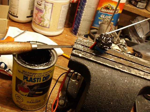
The terminals of the 10 amp miniature relay were potted with a rubber tool handle coating after the wires were soldered into place. The relay was secured to the left side, outside of the rear seat storage compartment so no storage space is lost.
A search under 3rd brake light or such should find the photos showing the modification of the tail light housing. A very simple and useful modification, IMO.
Hats off to the originator!
~~~
Thank You again for your contribution Norm Keller, STOC #8030
~~~
Third Brake Light ( ST1100 )
I added an H1 quartz bulb linked through a relay and load type flasher to the rear brake light wire.
It is a bit brighter than the other two (side) original brake lights but not enough to draw "official" disapproval. When the brake is applied, the three bulbs light and after about two seconds, the load type signal flasher begins to cycle which creates a very eye catching effect. I used an old KLR650 signal flasher because I wanted a delay before the flashing begins and an electronic or heavier load type begins to flash immediately.
Easy to do and, IMO, well worth the time required.
I seem not to be able to find photos of the bulb install but someone else posted these so they will be found.
Identify the brake light wire in the rear plug behind the under seat storage panel.
Remove the brake light terminal from the junction plug. Note that I do not like to cut into wiring and prefer to add the lead to the original plug in such a way that the system can be returned to stock if desired. The special tool is used to push the little latch lever in to allow the terminal to be withdrawn from the body of the plug. Bend the lever out again before sliding the terminal back into place.
Solder the lead wire to the terminal, positioned to allow the terminal to be replaced into the plug body. The other end of the lead wire has a female bullet connector to allow the third bulb harness to be connected or removed for service. By the way; if you are in the market for a solder gun for shop use, get one of these Wall LG400C units. Mac Tools sell them as do other sources. They are so superior to the transformer type made by Weller and such as to beggar comparison. The weight is a fraction and much more compact. 400 Watt output heats up in a few seconds and has enough go for heavy terminals. If that's not enough, get the 550 Watt element. I've seen them advertised for around $60 yes, I own one, and yes, I used to sell them. The other types are crap! As any alternator repair shop!
Power for the relay was taken from the fuse box and is live because the circuit is controlled by the brake light switch.
The terminals of the 10 amp miniature relay were potted with a rubber tool handle coating after the wires were soldered into place. The relay was secured to the left side, outside of the rear seat storage compartment so no storage space is lost.
A search under 3rd brake light or such should find the photos showing the modification of the tail light housing. A very simple and useful modification, IMO.
Hats off to the originator!
~~~
Thank You again for your contribution Norm Keller, STOC #8030
#20
ST1100 Archive of Wisdom / Additional Storage with Front ...
Last post by KoTAOW - October 05, 2017, 01:12:52 PMSubmitted by David Kunze, STOC #1155
~~~
Since some have expressed an interest in the following truly unique and custom farkle, I am posting additional information and photographs within this thread. Additional secured storage was obtained by installing a small pannier on the tip-over wings.
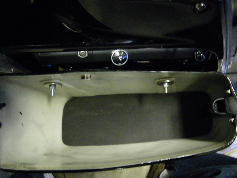
Here's a photo/farkle for the guys/gals who may ride two-up and prefer more cargo capacity for tools, spare parts, camping gear or anything else on your list... I allocate the trunk space for riding gear while parked and use the front bags for the heavier items such as tools, tent stakes, rain/cold weather gear or less frequently accessed items.
>Love the idea of the front hard bags. How did you mount them? <
I know the front bags are not for everyone. However, I don't care to shuffle things around that I don't use everyday simply to access things I do use every day, especially while traveling two-up or motorcycle camping. Most riders don't care to drag their tool bag, air compressor or spares into a hotel room or to sort their luggage in the parking lot.
The extra capacity is significant. The smaller bags hold a lot more than you may guess at first glance. Even the lids are shaped to accommodate more. A lot was gained and very little compromised by installing the bags.
The mounted front bags/panniers:
* are narrower than the width of the rear panniers and may be the same width of the mirrors.
* provide additional protection from the wind and rain.
* retain access to the oil fill cap (simply unlock and lift the lid)
* prevents tampering of the oil fill cap and spark plug wires
* provide additional leg protection while in an accident. I met an amputee once who lost his
leg due to a broadside collision with a car while on a motorcycle. (If packed with heavy items,
such as tools, the bags offer an additional buffer.)
* are secure with matching locks
* keep the cargo weight low and towards the front
* do not interfere with splitting lanes or moving the motorcycle
* do not interfere with rider's legs
* do not create any heat dissipation issues
* are mounted with only four bolts and may be removed quickly
* provides peace of mind by being more organized and packing bags according to frequency of use
* helps an owner become more self-reliant by packing more troubleshooting tools and spares.
* often fools the general public into thinking they are stock OEM bags or accessories
* become permanent once used for a while by spoiling the owner
Compromises:
* larger front profile and possibly less aerodynamic (ref photo)... perhaps a fuel tax?
* appearance for those strict 'form over function' folks
* Fortunately, I have not had an opportunity to crash test the panniers/bags.
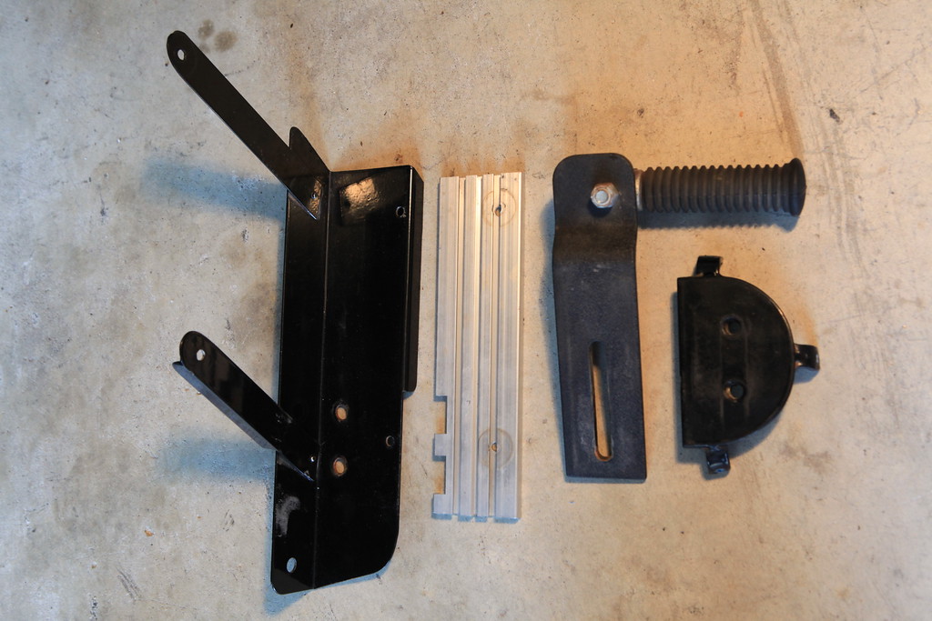
The installation is rather simple. I purchased:
* the bags on eBay from a company in San Francisco. ($135-ish in 2017)
GA Series Hard Saddlebags
* a pair of aftermarket ST1100 highway pegs & associated mounts (ref photo)
* Honda OEM markers and Pan American Logo
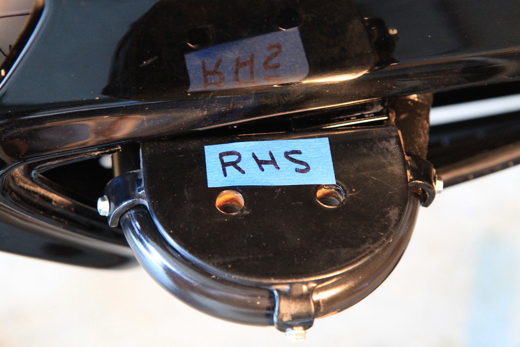
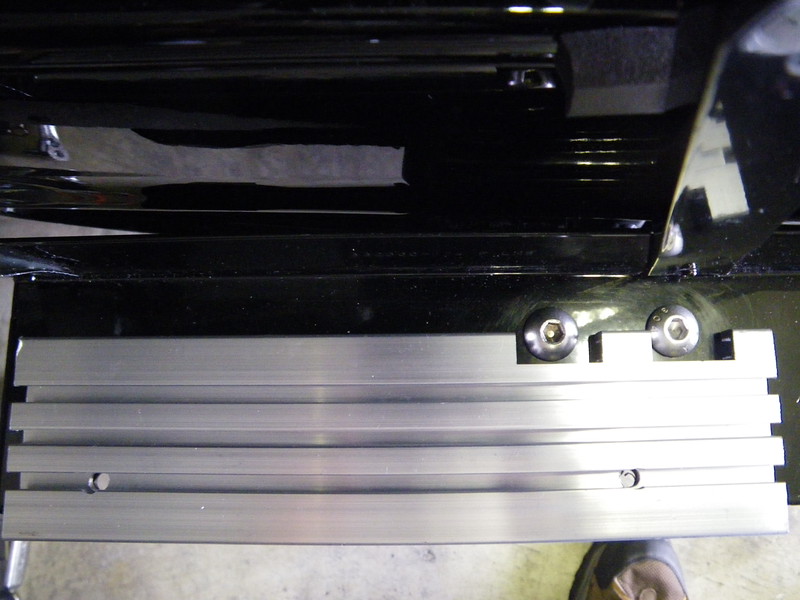
* services of a local fabrication shop to provide the mounting platform.
Btw, if you are careful while determining the placement of the front panniers, the maintenance covers may be removed while the front panniers are mounted.
I hope all these photographs inspire fellow riders, seeking additional storage, to consider a similar upgrade... just tell everyone it is Honda's 'grand touring' option.
Hopefully the following photographs are self-explanatory.
=========
>Why do you need that much storage capacity?<
Every rider is different and each of us have different hobbies, interests and priorities. I enjoy photography and travel with a lot photography equipment. As mentioned above, I like to have everything secured while parked and walking about in a park or in the city. (Don't give a thief an opportunity to disappoint you..) Therefore, my riding suit and boots utilize the trunk while parked. I use bag liners in the panniers and allocate one to my gal and one for myself or we share one and utilize the other for a small cooler containing food she prepared before leaving. (Her cooking is much healthier than the restaurants.) I suppose some may take advantage of hotels/restaurants and do not camp. I am sure many motorcycling-campers on this forum would like additional storage. When camping, additional volume is needed... sleeping bags and tents are not heavy. By utilizing the smaller aux. panniers for smaller items, additional space is available in the rear panniers for larger items. For three years I did not have a car/truck and used my motorcycle for everything. The extra capacity may be convenient for the daily riders without a second vehicle for daily errands such as going to the grocery store. As I mentioned in the original posts, I understand this mod isn't for everyone...
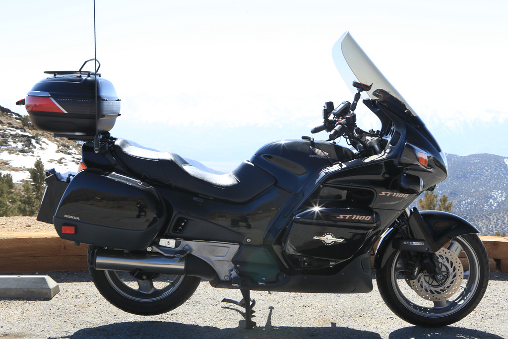
Finally, the motorcycle reflected in the photographs was recently sold to a fellow ST-Lister, Jim Aragon, and I believe he will attend WeSTOC next month. If you have additional questions not covered in the above, please feel free to send a PM or post to this thread.
(Many thanks to Jim Aragon for sharing the first photograph...my 'last ride' photograph.)
PS:
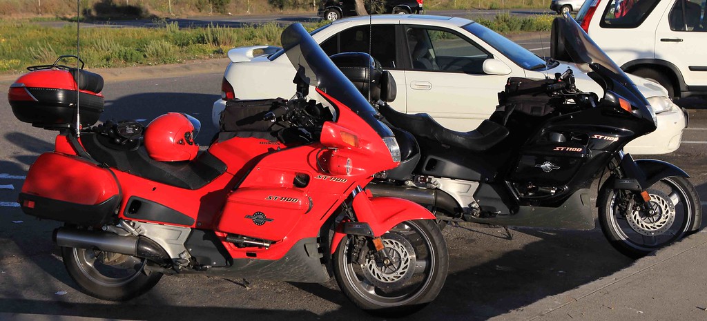
The farkle isn't totally unique... there's another ST1100A in red with the same grand touring option....
Btw, I would like to add the highway pegs are not usable, as hoped. Therefore, they are not required nor recommended for this installation.
Thank you & ride safely!
~~~
Thank You again for your contribution David Kunze, STOC #1155
~~~
Additional Storage with Front Panniers ( ST1100 )
Since some have expressed an interest in the following truly unique and custom farkle, I am posting additional information and photographs within this thread. Additional secured storage was obtained by installing a small pannier on the tip-over wings.
Here's a photo/farkle for the guys/gals who may ride two-up and prefer more cargo capacity for tools, spare parts, camping gear or anything else on your list... I allocate the trunk space for riding gear while parked and use the front bags for the heavier items such as tools, tent stakes, rain/cold weather gear or less frequently accessed items.
>Love the idea of the front hard bags. How did you mount them? <
I know the front bags are not for everyone. However, I don't care to shuffle things around that I don't use everyday simply to access things I do use every day, especially while traveling two-up or motorcycle camping. Most riders don't care to drag their tool bag, air compressor or spares into a hotel room or to sort their luggage in the parking lot.
The extra capacity is significant. The smaller bags hold a lot more than you may guess at first glance. Even the lids are shaped to accommodate more. A lot was gained and very little compromised by installing the bags.
The mounted front bags/panniers:
* are narrower than the width of the rear panniers and may be the same width of the mirrors.
* provide additional protection from the wind and rain.
* retain access to the oil fill cap (simply unlock and lift the lid)
* prevents tampering of the oil fill cap and spark plug wires
* provide additional leg protection while in an accident. I met an amputee once who lost his
leg due to a broadside collision with a car while on a motorcycle. (If packed with heavy items,
such as tools, the bags offer an additional buffer.)
* are secure with matching locks
* keep the cargo weight low and towards the front
* do not interfere with splitting lanes or moving the motorcycle
* do not interfere with rider's legs
* do not create any heat dissipation issues
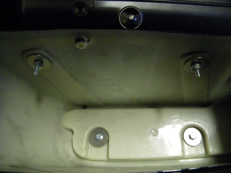
* are mounted with only four bolts and may be removed quickly
* provides peace of mind by being more organized and packing bags according to frequency of use
* helps an owner become more self-reliant by packing more troubleshooting tools and spares.
* often fools the general public into thinking they are stock OEM bags or accessories
* become permanent once used for a while by spoiling the owner
Compromises:
* larger front profile and possibly less aerodynamic (ref photo)... perhaps a fuel tax?
* appearance for those strict 'form over function' folks
* Fortunately, I have not had an opportunity to crash test the panniers/bags.
The installation is rather simple. I purchased:
* the bags on eBay from a company in San Francisco. ($135-ish in 2017)
GA Series Hard Saddlebags
* a pair of aftermarket ST1100 highway pegs & associated mounts (ref photo)
* Honda OEM markers and Pan American Logo
* services of a local fabrication shop to provide the mounting platform.
Btw, if you are careful while determining the placement of the front panniers, the maintenance covers may be removed while the front panniers are mounted.
I hope all these photographs inspire fellow riders, seeking additional storage, to consider a similar upgrade... just tell everyone it is Honda's 'grand touring' option.
Hopefully the following photographs are self-explanatory.
=========
>Why do you need that much storage capacity?<
Every rider is different and each of us have different hobbies, interests and priorities. I enjoy photography and travel with a lot photography equipment. As mentioned above, I like to have everything secured while parked and walking about in a park or in the city. (Don't give a thief an opportunity to disappoint you..) Therefore, my riding suit and boots utilize the trunk while parked. I use bag liners in the panniers and allocate one to my gal and one for myself or we share one and utilize the other for a small cooler containing food she prepared before leaving. (Her cooking is much healthier than the restaurants.) I suppose some may take advantage of hotels/restaurants and do not camp. I am sure many motorcycling-campers on this forum would like additional storage. When camping, additional volume is needed... sleeping bags and tents are not heavy. By utilizing the smaller aux. panniers for smaller items, additional space is available in the rear panniers for larger items. For three years I did not have a car/truck and used my motorcycle for everything. The extra capacity may be convenient for the daily riders without a second vehicle for daily errands such as going to the grocery store. As I mentioned in the original posts, I understand this mod isn't for everyone...
Finally, the motorcycle reflected in the photographs was recently sold to a fellow ST-Lister, Jim Aragon, and I believe he will attend WeSTOC next month. If you have additional questions not covered in the above, please feel free to send a PM or post to this thread.
(Many thanks to Jim Aragon for sharing the first photograph...my 'last ride' photograph.)
PS:
The farkle isn't totally unique... there's another ST1100A in red with the same grand touring option....
Btw, I would like to add the highway pegs are not usable, as hoped. Therefore, they are not required nor recommended for this installation.
Thank you & ride safely!
~~~
Thank You again for your contribution David Kunze, STOC #1155