- Welcome to ST-Riders - The liST.

The Original ST1100/ST1300 Forum
News:
Welcome to the liST! Before Posting, READ the liST rules stickie post Here! This is a private, STOC-members-only forum. Your real name and STOC# must appear in all posts. Failure to comply with these rules may result in your profile being changed, your account being suspended and/or your posts being removed.
Recent posts
#1
Welcome to ST-Riders / Re: Archives of Wisdom - Bot A...
Last post by Don Feyma - October 11, 2023, 02:10:18 PMOK, I'm going to try letting the AOW open to public access again - we'll see what happens. If the bots attack again, I may have to think of another strategy. 
#2
Welcome to ST-Riders / Re: Archives of Wisdom - Bot A...
Last post by Don Feyma - August 08, 2023, 09:26:17 AMQuote from: John OoSTerhuis on August 08, 2023, 09:19:10 AMDang.
Are you going to post that to SToners?
John
Yes, unless you want to.

I had over 100 bots on here at the same time this morning, most from the same domain, each on a different post on the AOW's 47.128.*.*
#3
Welcome to ST-Riders / Re: Archives of Wisdom - Bot A...
Last post by John OoSTerhuis - August 08, 2023, 09:19:10 AMDang.
Are you going to post that to SToners?
John
Are you going to post that to SToners?
John
#4
Welcome to ST-Riders / Archives of Wisdom - Bot Attac...
Last post by Don Feyma - August 08, 2023, 07:57:06 AMDue to the overwhelming numbers of bot attacks/copying on our Archives of Wisdom, I have been forced to restrict access to these forums to Members Only. Thanks for your understanding.
#5
ST1300 Archive of Wisdom / Replacing Halogen bulbs with F...
Last post by KoTAOW - December 15, 2019, 01:08:34 PMContributed by Keith Adams, STOC #8824.
~~~
* Remove fairings
* Disconnect halogen bulb
* Remove rubber boot
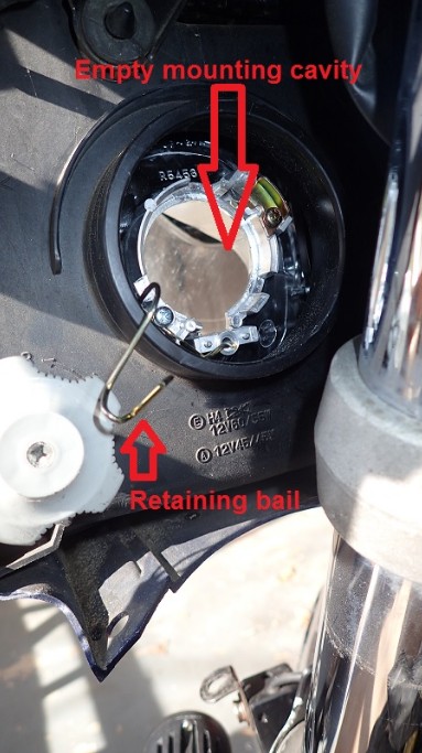
* Open wire retaining bail and remove halogen bulb
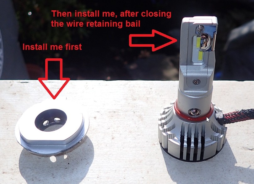
* Separate the mounting base from the emitter and fan assembly of the F2
* Remove the lower 2 tabs from the mounting plate (ST1300; not sure about the 1100).
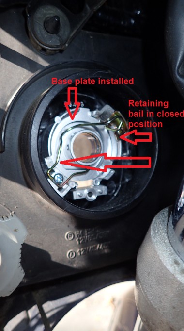
* Install the mounting plate and secure with the wire bail
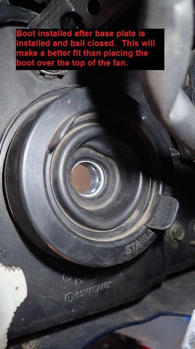
* Reinstall the rubber boot
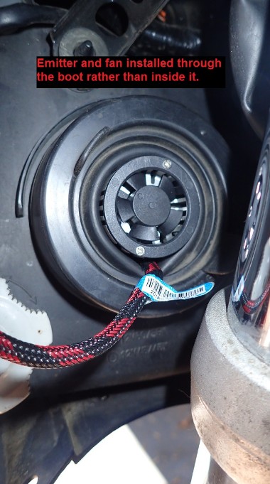
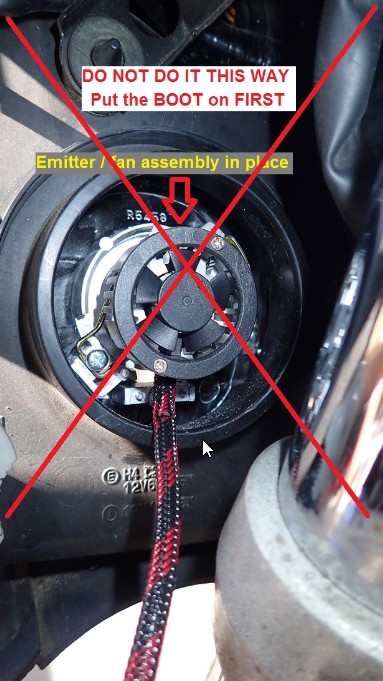
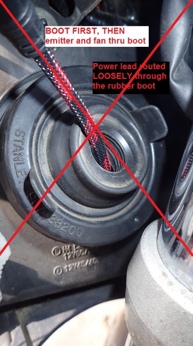
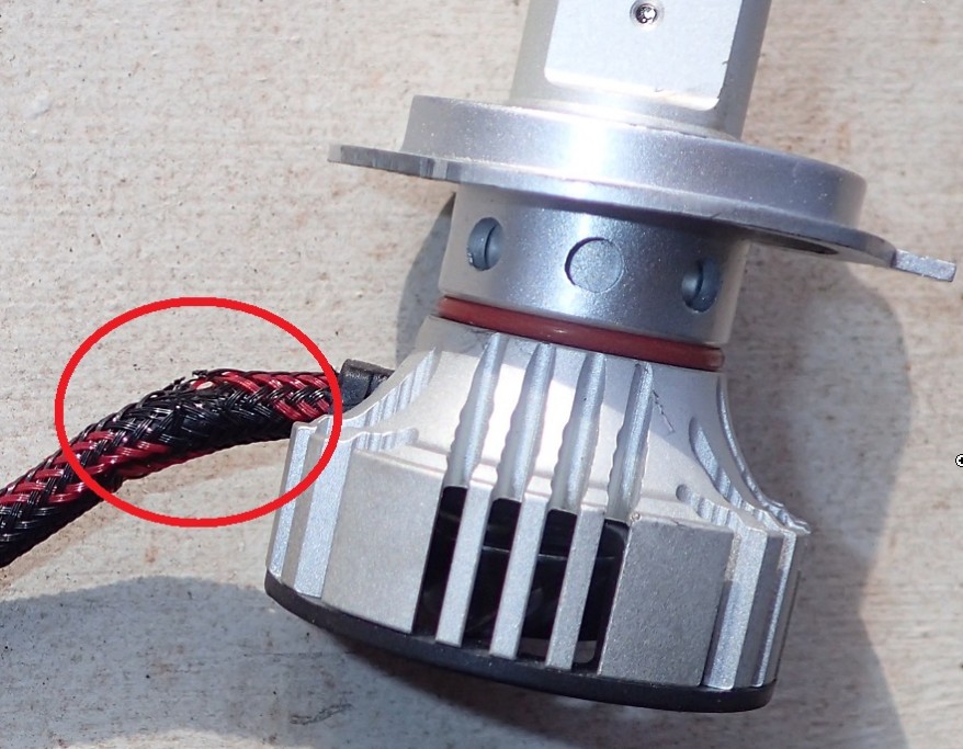
IMPORTANT: Install the boot BEFORE installing the emitter/fan assembly. I didn't do that on my first install because I didn't know that the base plate could be pulled off. That put the wire pigtail right against a hard plastic edge in the housing and after about 3,000 miles it had abraded to the point where a conductor was damaged and the light failed.
* Push LED emitters through center hole in boot and mounting plate; seat firmly and inspect from the front to ensure they are all the way through. The wiring pigtail coming off the fans should be at the bottom of the housing.
* Connect the wire pigtail from the bulb to the one from the power supply
* Connect power supply to OEM lighting harness using the stock 3-blade connector
Repeat on other side
* Power up and confirm proper aim, beam pattern, height. Adjust as needed. (Beam pattern is adjusted by rotating the emitters in the base.)
* Secure power supplies in convenient, not in the way locations
* Reinstall tupperware
* Go ride!
~~~
Thank You again for your contribution Keith Adams, STOC #8824
~~~
Replacing Halogen bulbs with F2 LED's ( ST1300 )
* Remove fairings
* Disconnect halogen bulb
* Remove rubber boot
* Open wire retaining bail and remove halogen bulb
* Separate the mounting base from the emitter and fan assembly of the F2
* Remove the lower 2 tabs from the mounting plate (ST1300; not sure about the 1100).
* Install the mounting plate and secure with the wire bail
* Reinstall the rubber boot
IMPORTANT: Install the boot BEFORE installing the emitter/fan assembly. I didn't do that on my first install because I didn't know that the base plate could be pulled off. That put the wire pigtail right against a hard plastic edge in the housing and after about 3,000 miles it had abraded to the point where a conductor was damaged and the light failed.
* Push LED emitters through center hole in boot and mounting plate; seat firmly and inspect from the front to ensure they are all the way through. The wiring pigtail coming off the fans should be at the bottom of the housing.
* Connect the wire pigtail from the bulb to the one from the power supply
* Connect power supply to OEM lighting harness using the stock 3-blade connector
Repeat on other side
* Power up and confirm proper aim, beam pattern, height. Adjust as needed. (Beam pattern is adjusted by rotating the emitters in the base.)
* Secure power supplies in convenient, not in the way locations
* Reinstall tupperware
* Go ride!
~~~
Thank You again for your contribution Keith Adams, STOC #8824
#6
ST1100 Archive of Wisdom / Ignition Relay ByPass Modifica...
Last post by Tom Melnik - November 21, 2019, 07:51:52 AMContributed by Jeff - STOC #8991.
Original article can be found here: Ignition Relay ByPass Mod (st-owners.com)
~~~
It appears there are two approaches; the "red wire bypass" and the "ignition relay bypass". The "red wire bypass" really does nothing other than trade one crimp for another. While this may work for a while (or long enough), it does not fix the issue. That 16 gauge red wire is still carrying all the current to power the bike, and I have read about people still having problems with melting connectors even after doing the red wire bypass. The ignition relay bypass actually fixes the issue by taking some of the load off of the red wire. Since I didn't want to have a nagging doubt about the red wire in the middle of nowhere, I decided to go with the ignition relay bypass method.
Norm Keller's excellent article in the AOW (http://www.st-riders.net/index.php?topic=3643.0) explains how the ignition relay bypass mod is implemented, so I'm only going to cover what I did differently.
On the '98 ABS/TCS, there are four wires that are switched through the ignition:
Wire 1: ABS Main (10A, Red/Black)
Wire 2: Fan Motor (10A, Blue/Orange)
Wire 3: Position, Meter Light, Tail, Neutral, Oil, Temp, Tacho, Horn (10A, Red/Black)
Wire 3: Ignition, Starter, Alternator (10A)
Wire 3: Turn Signal, Brake (10A)
Wire 4: Accessory (5A)
I decided to bypass wires 1, 2, and 3 and use wire 4 to energize the relay.
I didn't want to cut the three wires at the fuse box and use butt connectors, so that meant obtaining the right fuse box terminals. I located a source for the single fuse connectors (Eastern Beaver) but they didn't have the bused connector for wire 3. I thought I had found a source for the Bused Connector (link) but as you'll see in the picture below, what they sent me was something different than what is pictured for that item on Amazon. But I was able to modify it to make it work.
I didn't use anything that came pre-crimped.
On the right is the bused strip of three connectors that I made from the strip on the left that was shipped to me:
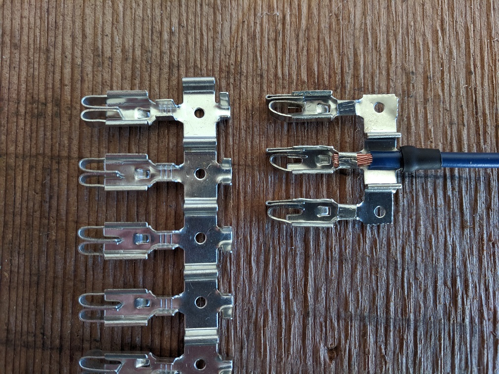
Yes, I could have used three single connectors in place of the bused connector, but then I would have had five wires coming back to the relay and I didn't want that.
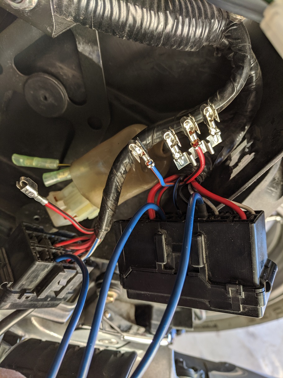
Here, the new wires (14 gauge) are installed in the fuse boxes after removing the existing connectors:
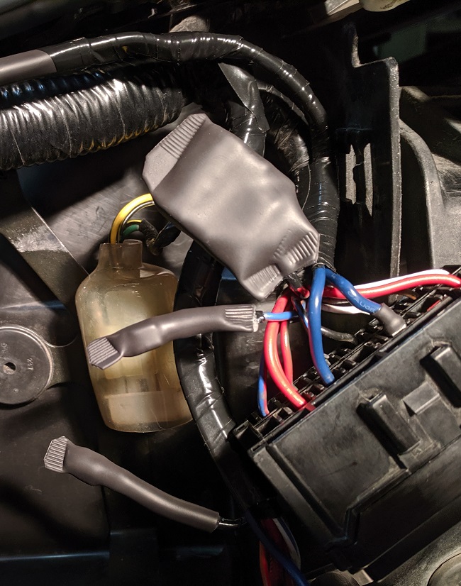
I taped and shrink wrapped the removed connectors to insulate them:
Doing it this way makes the mod easily reversible although I don't know why anyone would want to do that.
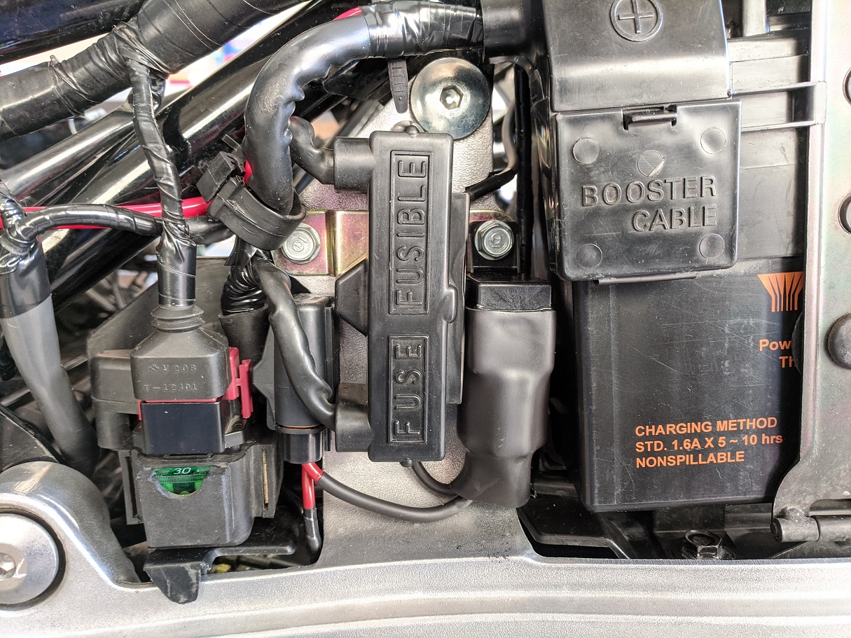
I put a 90° bend in the ring terminal at the starter relay so that the rubber cover would fit over it (used 12 gauge wire):
Crimped the male part of a bullet connector onto the wire going to the accessory circuit:
For the relay ground, I used the bolt behind the handle that is used to lever the bike onto its center stand.
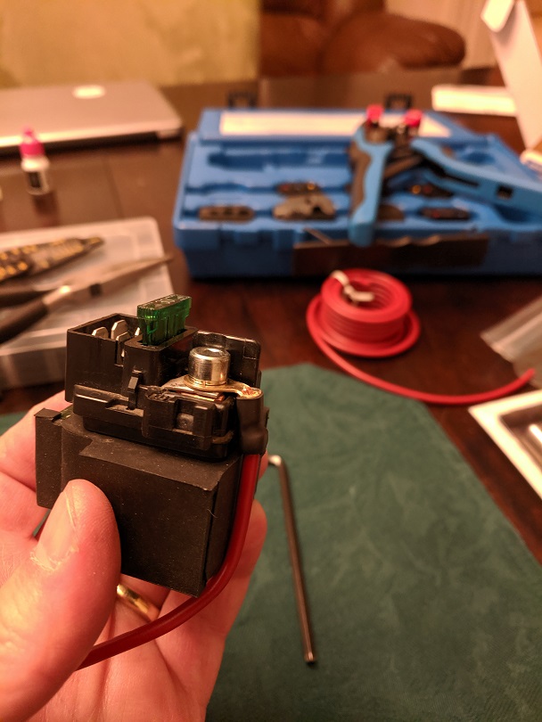
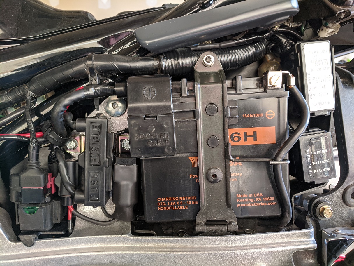
There's not much room between the alternator fuse and the battery to fit a relay, but the 40 amp sealed mini relay and base holder (link) from Cycle Terminal fit perfectly and I was able to mount it using the bolt to the right of the alternator fuse:
Here's what it looks like all buttoned up. I shrink wrapped the relay to keep moisture out:
I did not think to measure the voltage drop before I started, but I measured after I was done and it was only 0.06V between the battery and the fuse box.
~~~~~~
Edit:
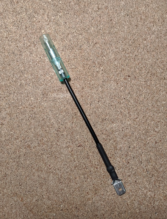
For those without the accessory circuit (the 28-amp alternator bikes), here is a way to get switched power for the relay without cutting a fuse box wire.
Take a short piece of wire and crimp a male spade connector on one end and a female bullet connector on the other:
Push the spade connector onto the fuse terminal of the Red/Black wire:
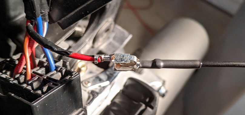
Tape tightly and shrink wrap:
~~~~~~~~~~~~~~~~~~~~~~~~~~~~~~~~~~~~~~~~~~~~~~~~
NOTE: Attached below is a Wiring\Schematic of this modification (PDF)
~~~~~~~~~~~~~~~~~~~~~~~~~~~~~~~~~~~~~~~~~~~~~~~~
One is less likely to have a problem with the ignition switch than the red wire I imagine, but I have read a few accounts of it happening as these ST1100s age. While working on the ignition bypass relay, I realized that should there ever be a problem with the ignition switch while on a trip, it would be easy to install a toggle switch between the relay and the battery to bypass the ignition switch entirely. So I took a toggle switch and put a ring terminal on one wire and a female bullet connector on the other wire.
Now if there is a problem with the ignition switch, I just have to remove the battery, unplug the bullet connector from the accessory circuit and plug it into the connector on the toggle switch. Then connect the ring terminal to the battery positive and I'm on my way.
EDIT: When I tested it, everything powered up except for the headlights. I went back and looked at the wiring diagram and discovered that the low and high beam relays are energized by the ignition wire (IE: the same Red\Black wire as Wires #1 & #3 in original post).
I therefore added a second connector to the harnes (see below).
EDIT:
Final version. Added second connector to power headlight relays. This plugs into the Red\Black wire. Also added 3 amp in-line fuse.
~~~
Thank You again for your contribution Jeff - STOC #8991
Original article can be found here: Ignition Relay ByPass Mod (st-owners.com)
~~~
Ignition Relay ByPass Modification 2.0 ( ST1100 )
It appears there are two approaches; the "red wire bypass" and the "ignition relay bypass". The "red wire bypass" really does nothing other than trade one crimp for another. While this may work for a while (or long enough), it does not fix the issue. That 16 gauge red wire is still carrying all the current to power the bike, and I have read about people still having problems with melting connectors even after doing the red wire bypass. The ignition relay bypass actually fixes the issue by taking some of the load off of the red wire. Since I didn't want to have a nagging doubt about the red wire in the middle of nowhere, I decided to go with the ignition relay bypass method.
Norm Keller's excellent article in the AOW (http://www.st-riders.net/index.php?topic=3643.0) explains how the ignition relay bypass mod is implemented, so I'm only going to cover what I did differently.
On the '98 ABS/TCS, there are four wires that are switched through the ignition:
Wire 1: ABS Main (10A, Red/Black)
Wire 2: Fan Motor (10A, Blue/Orange)
Wire 3: Position, Meter Light, Tail, Neutral, Oil, Temp, Tacho, Horn (10A, Red/Black)
Wire 3: Ignition, Starter, Alternator (10A)
Wire 3: Turn Signal, Brake (10A)
Wire 4: Accessory (5A)
I decided to bypass wires 1, 2, and 3 and use wire 4 to energize the relay.
I didn't want to cut the three wires at the fuse box and use butt connectors, so that meant obtaining the right fuse box terminals. I located a source for the single fuse connectors (Eastern Beaver) but they didn't have the bused connector for wire 3. I thought I had found a source for the Bused Connector (link) but as you'll see in the picture below, what they sent me was something different than what is pictured for that item on Amazon. But I was able to modify it to make it work.
I didn't use anything that came pre-crimped.
On the right is the bused strip of three connectors that I made from the strip on the left that was shipped to me:
Yes, I could have used three single connectors in place of the bused connector, but then I would have had five wires coming back to the relay and I didn't want that.
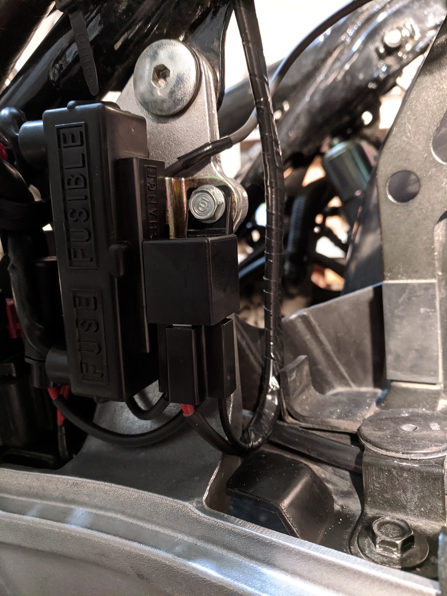
Here, the new wires (14 gauge) are installed in the fuse boxes after removing the existing connectors:
I taped and shrink wrapped the removed connectors to insulate them:
Doing it this way makes the mod easily reversible although I don't know why anyone would want to do that.
I put a 90° bend in the ring terminal at the starter relay so that the rubber cover would fit over it (used 12 gauge wire):
Crimped the male part of a bullet connector onto the wire going to the accessory circuit:
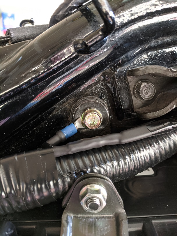
For the relay ground, I used the bolt behind the handle that is used to lever the bike onto its center stand.
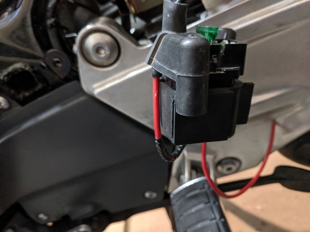
There's not much room between the alternator fuse and the battery to fit a relay, but the 40 amp sealed mini relay and base holder (link) from Cycle Terminal fit perfectly and I was able to mount it using the bolt to the right of the alternator fuse:
Here's what it looks like all buttoned up. I shrink wrapped the relay to keep moisture out:
I did not think to measure the voltage drop before I started, but I measured after I was done and it was only 0.06V between the battery and the fuse box.
~~~~~~
Edit:
For those without the accessory circuit (the 28-amp alternator bikes), here is a way to get switched power for the relay without cutting a fuse box wire.
Take a short piece of wire and crimp a male spade connector on one end and a female bullet connector on the other:
Push the spade connector onto the fuse terminal of the Red/Black wire:
Tape tightly and shrink wrap:
~~~~~~~~~~~~~~~~~~~~~~~~~~~~~~~~~~~~~~~~~~~~~~~~
NOTE: Attached below is a Wiring\Schematic of this modification (PDF)
~~~~~~~~~~~~~~~~~~~~~~~~~~~~~~~~~~~~~~~~~~~~~~~~
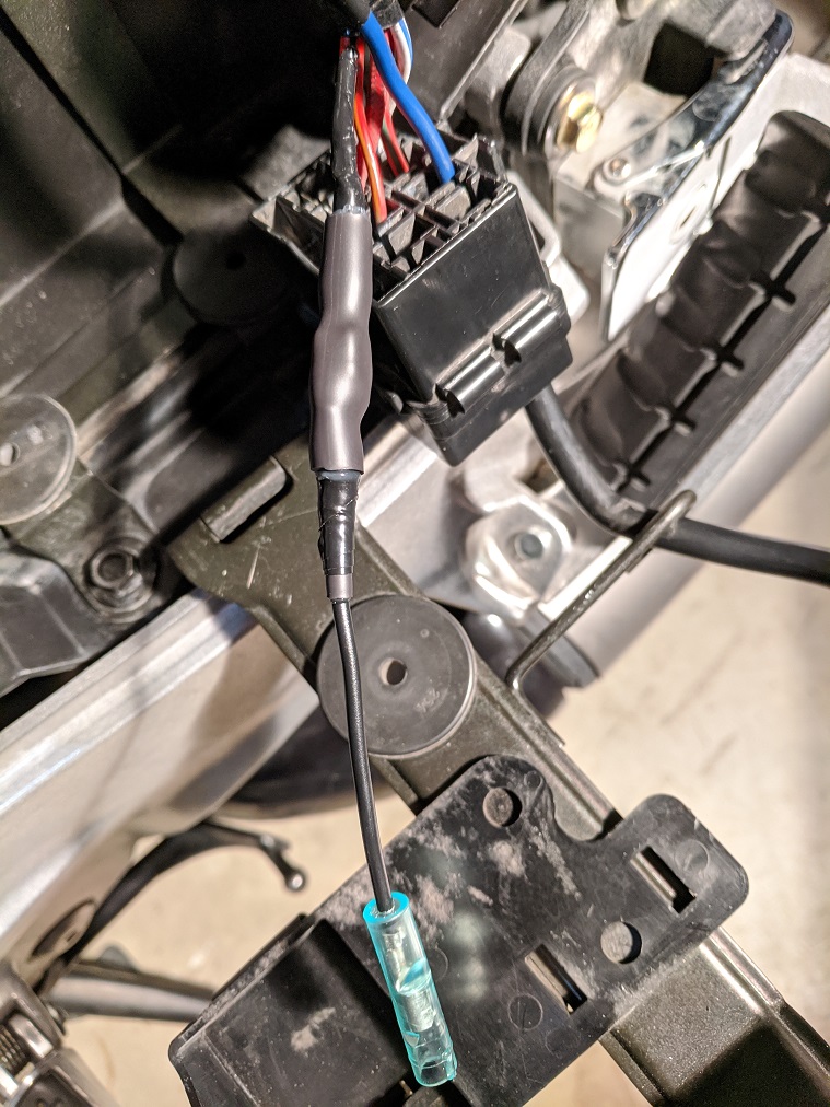
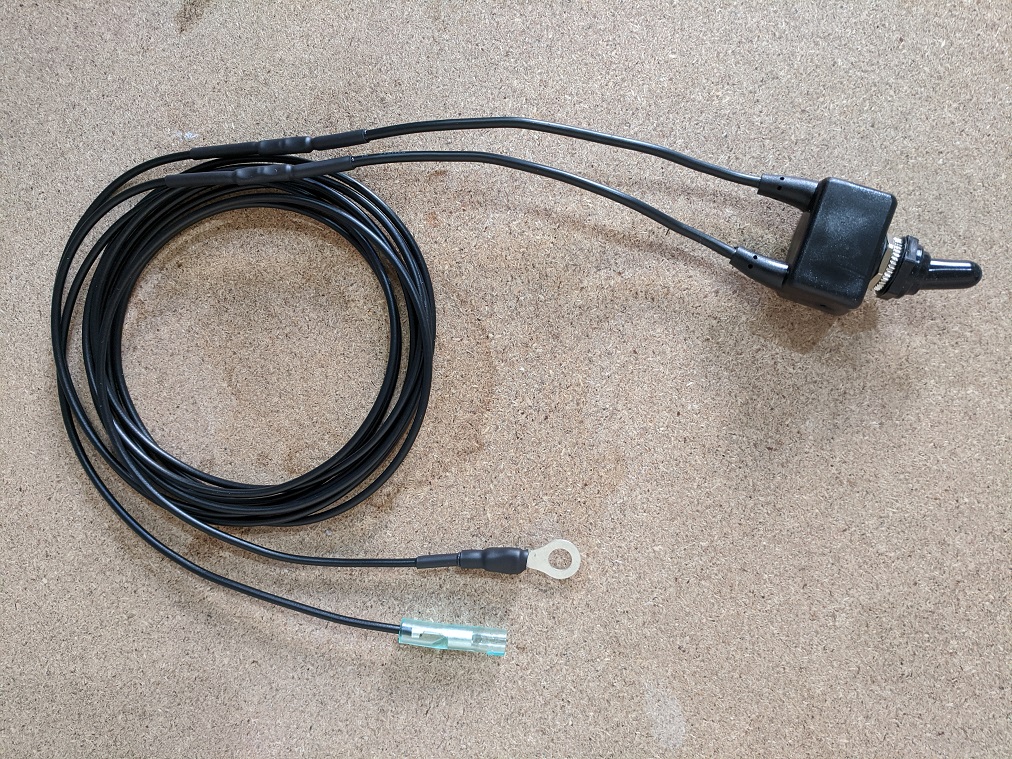
One is less likely to have a problem with the ignition switch than the red wire I imagine, but I have read a few accounts of it happening as these ST1100s age. While working on the ignition bypass relay, I realized that should there ever be a problem with the ignition switch while on a trip, it would be easy to install a toggle switch between the relay and the battery to bypass the ignition switch entirely. So I took a toggle switch and put a ring terminal on one wire and a female bullet connector on the other wire.
Now if there is a problem with the ignition switch, I just have to remove the battery, unplug the bullet connector from the accessory circuit and plug it into the connector on the toggle switch. Then connect the ring terminal to the battery positive and I'm on my way.
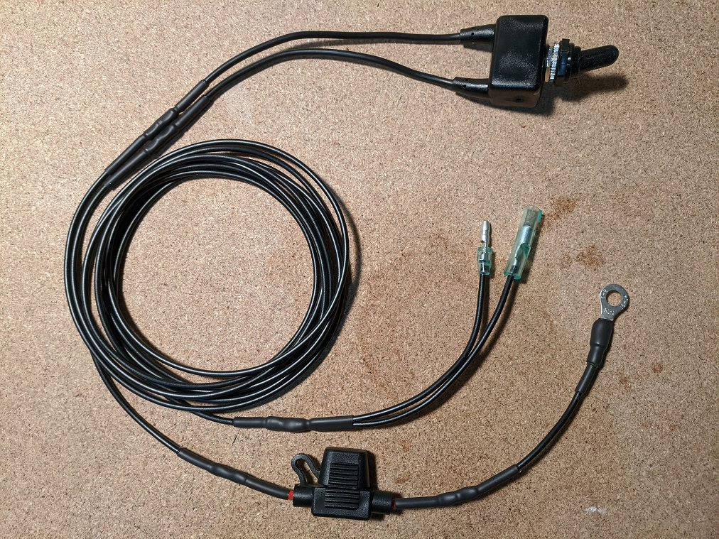
EDIT: When I tested it, everything powered up except for the headlights. I went back and looked at the wiring diagram and discovered that the low and high beam relays are energized by the ignition wire (IE: the same Red\Black wire as Wires #1 & #3 in original post).
I therefore added a second connector to the harnes (see below).
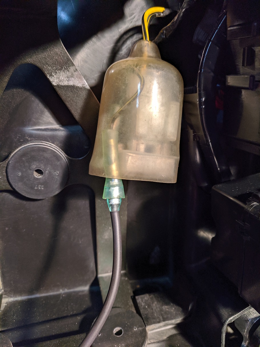
EDIT:
Final version. Added second connector to power headlight relays. This plugs into the Red\Black wire. Also added 3 amp in-line fuse.
~~~
Thank You again for your contribution Jeff - STOC #8991
#7
ST1300 Archive of Wisdom / Re: Tony Worrall's "Pendle Par...
Last post by KoTAOW - September 12, 2018, 07:13:29 PMComments by Scott Chaisson, STOC #8642: It's important to note that you should adjust the brake first, before you drill. The hole changes when the brake is adjusted.
At least, that's the way it seems to me on my bike. I've had it for ~2 years now. Works very well.
At least, that's the way it seems to me on my bike. I've had it for ~2 years now. Works very well.
#8
ST1100 Archive of Wisdom / Dash Shelf ( ST1100 ) *
Last post by KoTAOW - September 12, 2018, 07:09:56 PMContributed by Adrian, aka Totgas, STOC #XXXX.
Original article here: http://www.ozstoc.com/index.php?topic=7622.msg87584#msg87584
~~~
Items Needed:
• Aluminum sheet metal at least 2 mm/0.079" thick and checkerboard pattern
• Angle grinder
• Straight file
• Different grades of sandpaper
• Rubber mallet
• Hacksaw blade
• Drill and 2 mm/0.079" & 5 mm/0.197" drill bits
• Scribe or sharp nail
• Paint â€" metal primer and topcoat (recommend matt black)
• Vice
• 1hr not including paint drying time
• Small washers â€" Optional (6)
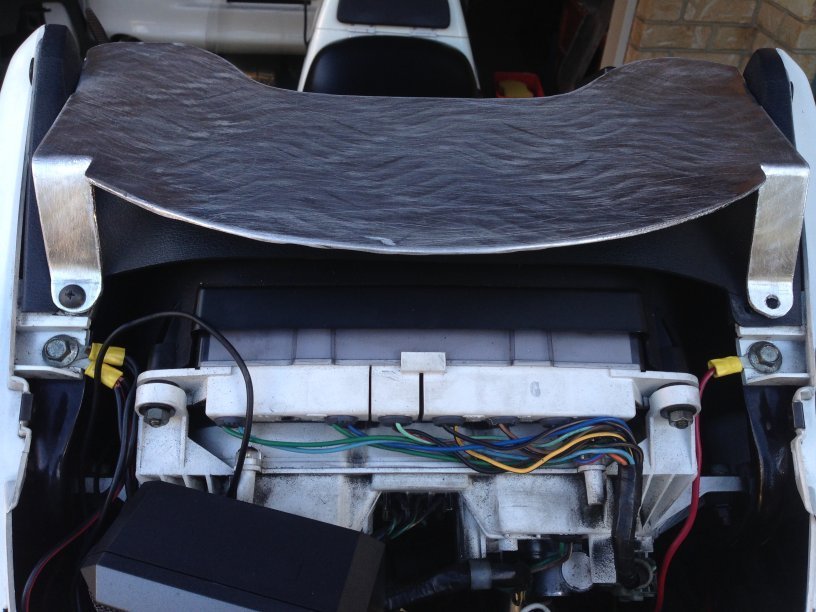
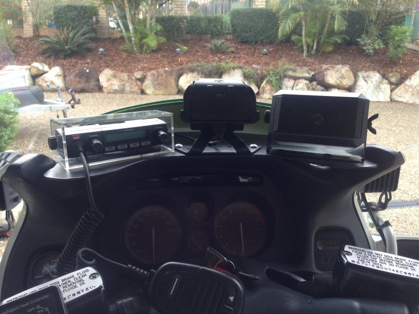
Note: the shape of this shelf (my own design) maximises available space without restricting your view of the warning lights.
I recently bought a new GPS (A TomTom Rider) to replace the ALDI one I had had for the last 4 years (A Go-Cruise) Great GPS â€" much maligned.
My original dash shelf was made of light weight metal and as a result the TomTom bounced around quite a lot.
First off I made a new mounting bracket instead of using the ram mount that came with the TomTom (as it was quite high) but the bounce continued. My plan was therefore to remove the bounce from the dash shelf by making a second shelf this time out of a much thicker material.
So off to Bunnings and I picked up a 2 mm/0.079" Checkerboard Aluminum sheet for $34.00.
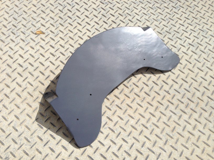
My original 1mm shelf I was able to cutout with tin snips but this one was a little harder so I decided on the angle grinder. I removed my windscreen and then the existing shelf, bashed it with a rubber hammer (until it was quite dead and flat) and made up a template which needs to be mirrored.
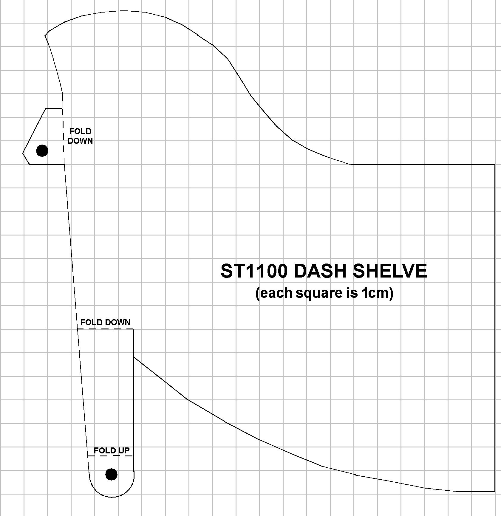
After tracing the image on the back of the metal sheet I cut out the shape with the grinder. There was plenty of sheet left over for the next project.
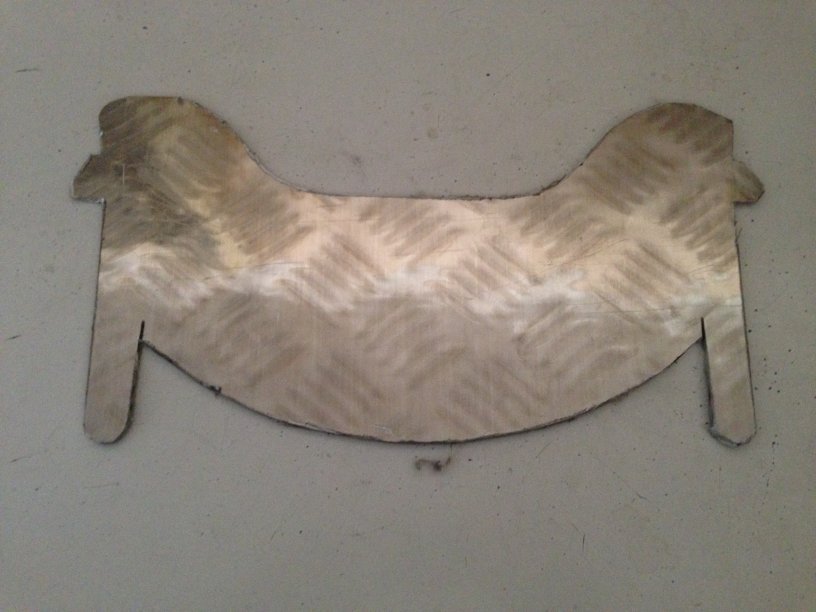
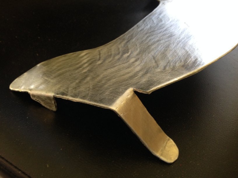
However as you can see the grinder leave a fairly rough edge
So the first order of business is to remove all the rough edges with a file then sandpaper. Don’t be tempted to use a mechanical sanding device as it will damage the edges.
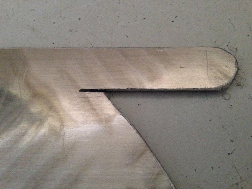
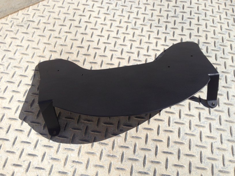
Finally sand the entire underside of the plate (which is actually the top of the shelf) as this creates a nice rough surface for the paint to bond to. Also using a hacksaw blade tidy up the cuts next to the front legs.
Place the shelve in the vice and using a rubber mallet bend the legs and side tabs accordingly. (I always bend these the wrong way initially so think about the direction they need to go in)
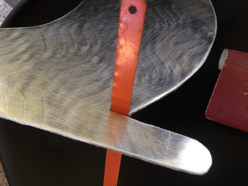
Now drill the holes with a 2 mm/0.079" drill and then the 5 mm/0.197". The holes need to be reasonably close to the edge as below.
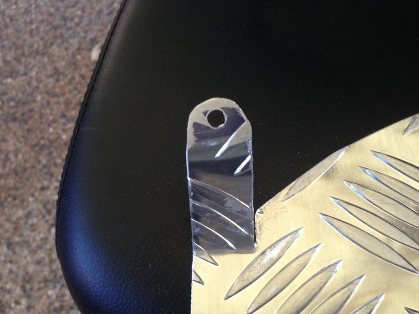
With this done, you are ready for a test fit. I will guarantee that the holes will not align 100%.
However, the fact that we have made this out of aluminum means that the legs can be adjusted to fit perfectly. (Hint â€" always fit the side tabs first and never tighten any bolt up until all are in place)
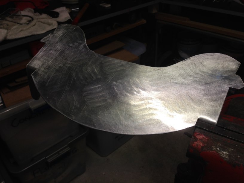
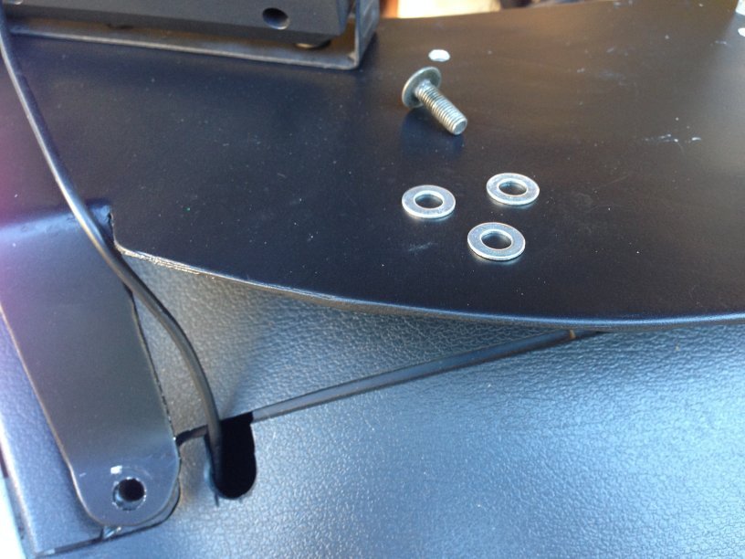
Time for a final sand, clean and spray with a suitable primer for aluminum. (Hint â€" If you are going to mount accessories on the shelf [isn’t that what it’s for] and you know exactly where they are going, then drill the holes now).
I use dry gal as my primer for everything and it works fine.
After a suitable drying time (1hr for the Gal) spray the top coat or two.
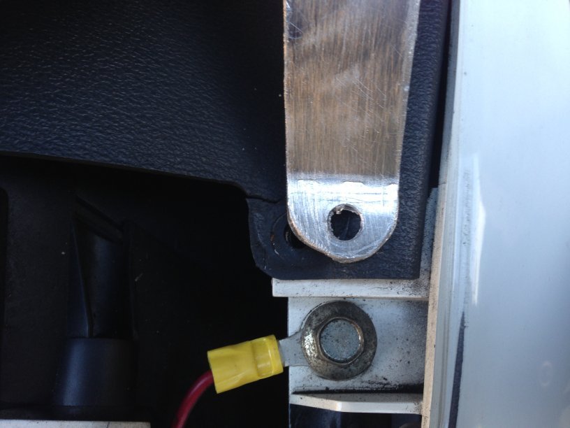
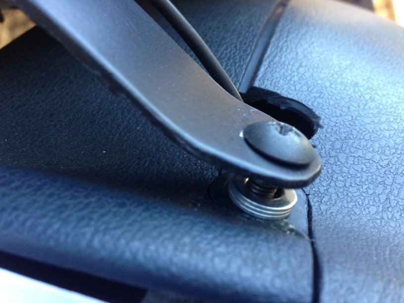
Nearly there….. One final tip the front legs will be sitting on plastic that is not completely flat. If you are anal like me about your bike, you may want the stick three small washers together to place them between the leg and the plastic, this will prevent the plastic cracking over time â€" trust me)
Fit and farklise…
~~~
Thank You again for your contribution Adrian, aka Totgas, STOC #XXXX
Original article here: http://www.ozstoc.com/index.php?topic=7622.msg87584#msg87584
~~~
Dash Shelf ( ST1100 )
Items Needed:
• Aluminum sheet metal at least 2 mm/0.079" thick and checkerboard pattern
• Angle grinder
• Straight file
• Different grades of sandpaper
• Rubber mallet
• Hacksaw blade
• Drill and 2 mm/0.079" & 5 mm/0.197" drill bits
• Scribe or sharp nail
• Paint â€" metal primer and topcoat (recommend matt black)
• Vice
• 1hr not including paint drying time
• Small washers â€" Optional (6)
Note: the shape of this shelf (my own design) maximises available space without restricting your view of the warning lights.
I recently bought a new GPS (A TomTom Rider) to replace the ALDI one I had had for the last 4 years (A Go-Cruise) Great GPS â€" much maligned.
My original dash shelf was made of light weight metal and as a result the TomTom bounced around quite a lot.
First off I made a new mounting bracket instead of using the ram mount that came with the TomTom (as it was quite high) but the bounce continued. My plan was therefore to remove the bounce from the dash shelf by making a second shelf this time out of a much thicker material.
So off to Bunnings and I picked up a 2 mm/0.079" Checkerboard Aluminum sheet for $34.00.
My original 1mm shelf I was able to cutout with tin snips but this one was a little harder so I decided on the angle grinder. I removed my windscreen and then the existing shelf, bashed it with a rubber hammer (until it was quite dead and flat) and made up a template which needs to be mirrored.
After tracing the image on the back of the metal sheet I cut out the shape with the grinder. There was plenty of sheet left over for the next project.
However as you can see the grinder leave a fairly rough edge
So the first order of business is to remove all the rough edges with a file then sandpaper. Don’t be tempted to use a mechanical sanding device as it will damage the edges.
Finally sand the entire underside of the plate (which is actually the top of the shelf) as this creates a nice rough surface for the paint to bond to. Also using a hacksaw blade tidy up the cuts next to the front legs.
Place the shelve in the vice and using a rubber mallet bend the legs and side tabs accordingly. (I always bend these the wrong way initially so think about the direction they need to go in)
Now drill the holes with a 2 mm/0.079" drill and then the 5 mm/0.197". The holes need to be reasonably close to the edge as below.
With this done, you are ready for a test fit. I will guarantee that the holes will not align 100%.
However, the fact that we have made this out of aluminum means that the legs can be adjusted to fit perfectly. (Hint â€" always fit the side tabs first and never tighten any bolt up until all are in place)
Time for a final sand, clean and spray with a suitable primer for aluminum. (Hint â€" If you are going to mount accessories on the shelf [isn’t that what it’s for] and you know exactly where they are going, then drill the holes now).
I use dry gal as my primer for everything and it works fine.
After a suitable drying time (1hr for the Gal) spray the top coat or two.
Nearly there….. One final tip the front legs will be sitting on plastic that is not completely flat. If you are anal like me about your bike, you may want the stick three small washers together to place them between the leg and the plastic, this will prevent the plastic cracking over time â€" trust me)
Fit and farklise…
~~~
Thank You again for your contribution Adrian, aka Totgas, STOC #XXXX
#9
ST1300 Archive of Wisdom / Tony Worrall's "Pendle Parking...
Last post by KoTAOW - August 26, 2018, 09:00:19 AMContributed by Michael Moore, STOC #2636.
~~~
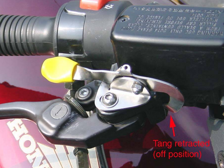
I bought a ST 1300 a couple of months ago, and the one gadget I missed the most on the new 1300 was the Middleton Handbrake that I have had on my ST 1100 for the past 10 years. For those of you who didn't have an ST during the last century, the Middleton Handbrake was a clever little bit of stainless steel origami that allowed the rider to set the front brake to remain on. The park brake released automatically when the front brake lever was pulled in a bit further. It worked by putting a small tang in behind the brake lever when the brake lever was applied and the handbrake lever was moved up by the rider's thumb or forefinger. Clever and elegant engineering at its best.
With the handbrake fitted on your ST 1100, you could set it with a flick of the finger when at a stoplight, or parked at the side of the road looking at a map, or in any other situation where you didn't want the moto to roll in either direction, but wanted to be able to take your hand (and foot) off the brake lever. I used it constantly.
Middleton Handbrake for ST 1100
Mr. Middleton ran (runs?) a stainless steel shop in the UK. My guess is that he also rode a ST 1100, and developed this little goodie on his own. Unfortunately, it seems that he never bought a ST 1300 (and probably sold his ST 1100), because the original ST 1100 handbrake is now out of production, and there never was a handbrake made for the ST 1300.
...until Tony Worrall came along.
Tony (whom I am going to guess is a ST 1300 owner) has designed and is currently manufacturing and shipping handbrake kits for the ST 1300. I ordered a kit from him a couple of weeks ago, and when it arrived by post, I installed it on my ST 1300.
Here's what the contents of the kit look like:
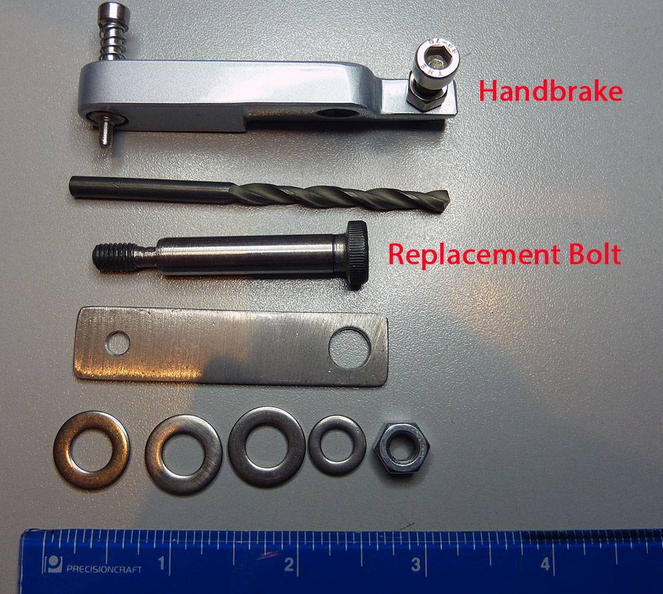
Only the handbrake lever (top part) and the replacement brake lever bolt are actually installed on the ST 1300. The drill bit, flat piece of metal with the two holes, the nut and the washers are used during the installation process, and discarded afterwards.
The shape of the ST 1300 brake lever and the placement of the throttle cables is such that the original Middleton design cannot be used on the ST 1300. There's not enough space available - the throttle cables are in the way. Additionally, the inboard end of the brake lever is a little different on the 1300, and doesn't present an easy opportunity to slide a tang into place to keep the brake applied.
Tony has followed a different path designing his handbrake. Instead of attempting to keep the front brake applied by sticking something into the far inboard end of the brake lever, he's designed a device that fits into a small dimple (hole) drilled into the top of the front handbrake lever. The general principle is the same, though: To use it, you squeeze the front brake lever in the normal way, then press down on the top of a spring-loaded pin that is captive in the end of a bar mounted above the brake lever. This inserts the pin into the hole in the top of the lever. The pin is spring-loaded to pop up out of the hole in the brake lever, and the hole is larger than the pin. Thus, any further squeezing of the brake lever once the parking brake is applied will cause the pin to pop up and the handbrake to release. It works well.
Tony provides a complete set of illustrated instructions with the kit (the instructions are also available at his website, click here). I'm not going to attempt to duplicate his instructions here, but rather to provide a general overview of how the thing works, and what is involved in installing it.
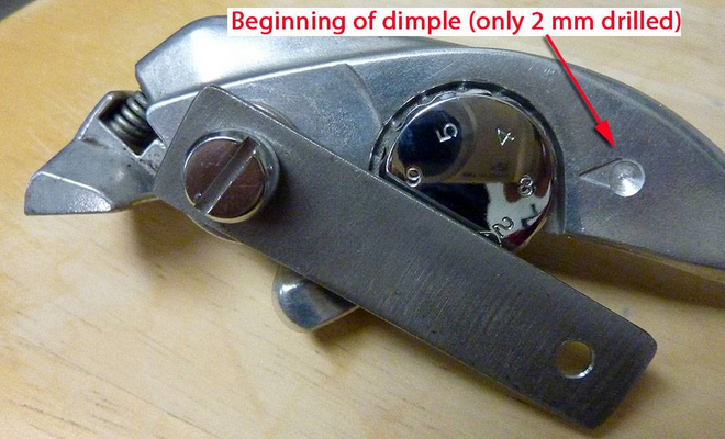
First, you remove the front brake lever, and using the existing Honda bolt and the washers, nut, and drilling template that Tony provides, you mount the drilling template onto the top of the handbrake lever. The smaller hole on on the drilling template, on the right side of the picture below, shows where the hole will be drilled in the handbrake lever.
Drilling Template Mounted
The hole will be drilled more or less at the outboard end of the arrow embossed on the lever.
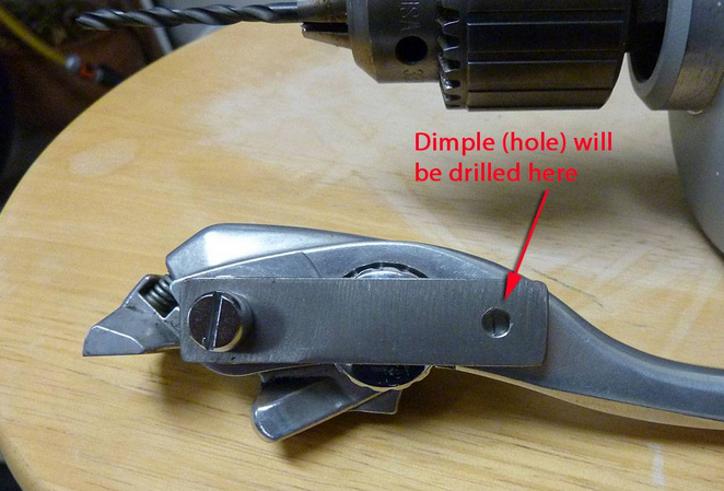
Hole Partially Drilled
I had to sneak a peek. The handgrip is 18 mm thick at this point, the hole will only be 5 mm deep
Hole Drilled, Everything Re-Installed
How it works (pin movement up and down into hole)
How it is Applied
To release it, just slightly squeeze the brake lever in the normal manner, no need to touch the parking brake, it will pop up.
What it looks like when Applied
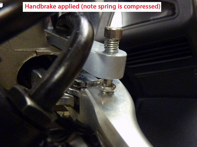
I was a bit apprehensive about the idea of drilling a hole partway into the front brake lever. But, after thinking about it for a bit, I realized that the hole (a dimple, actually) is only 4 mm deep, and the handbrake lever is 18 mm thick at the point where the hole gets placed. Besides, Honda has already drilled a much larger hole completely through the handbrake lever casting - up where it pivots to apply the brake (where the bolt goes) - and I have heard no reports of the casting breaking where Honda put their hole.
I was also kind of apprehensive about my limited skill drilling holes in metal, but the task was made pretty simple by the template and drill bit that Tony provides. The only thing I had to pay attention to was making sure I did not drill any deeper than the 4 to 6 mm specified (final depth of my hole was 4.5 mm).
All told, it took about 30 minutes to carry out this installation, and 10 minutes of that time was fetching the drill and then putting the drill away.
The Pendle Parking Brake for the ST 1300 works as well as the original Middleton design for the ST 1100. I'm very happy with it, and recommend it without reservation to others. Be aware that it is only intended to be used when the rider is astride the motorcycle - in other words, if you want to park your bike on a hill using the side-stand, you put the engine in gear as you normally would. This handbrake would hold the moto parked on a hill, but if anyone bumps the front brake lever, the handbrake will instantly release, as it is designed to do.
The only addition I would make to the otherwise excellent instructions that Tony provides with the kit is to suggest that after installing everything, you apply a little bit of oil to the spring-loaded pin that goes up and down, to ensure that it extends and retracts easily and without any friction. It would be nice if the button on top of the spring-loaded pin was bigger... I'm going to keep my eyes open for something that I can put over it to provide a larger surface to push on. But, there is no problem operating the pin as it is now.
Tony sells these parking brakes on eBay for ₤30 ( about $50 US Dollars), shipping included. You'll have to go on eBay and search for "Pendle Parking Brake" to find it. His website, which contains information and installation instructions, is here. I believe that he sells a similar device for the ST 1100, but I am not familiar with that device.
~~~
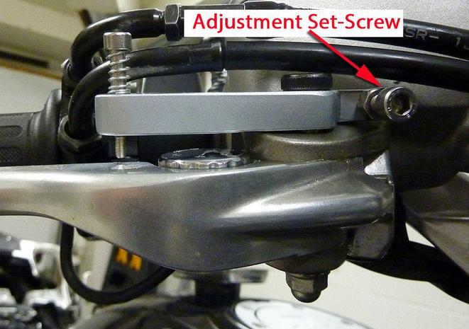
Ooops, I forgot to mention that the amount of pressure that the handbrake exerts when applied can be adjusted using a small set-screw at the inboard end of the lever. Because this facility for adjustment is provided, fore and aft placement of the hole (when drilling it) is not critical. I chose to try and center the hole front to back in the brake lever, I think that position minimizes the risk of any cracks propagating in the casting as a result of the hole being drilled.
The adjustment set-screw allows for brake lever position to be changed using the chrome dial on the brake lever without any loss of efficiency of the parking brake.
Adjustment Set-Screw
~~~
Thank You again for your contribution Michael Moore, STOC #2636
~~~
Tony Worrall's "Pendle Parking Brake" ( ST1300 )
I bought a ST 1300 a couple of months ago, and the one gadget I missed the most on the new 1300 was the Middleton Handbrake that I have had on my ST 1100 for the past 10 years. For those of you who didn't have an ST during the last century, the Middleton Handbrake was a clever little bit of stainless steel origami that allowed the rider to set the front brake to remain on. The park brake released automatically when the front brake lever was pulled in a bit further. It worked by putting a small tang in behind the brake lever when the brake lever was applied and the handbrake lever was moved up by the rider's thumb or forefinger. Clever and elegant engineering at its best.
With the handbrake fitted on your ST 1100, you could set it with a flick of the finger when at a stoplight, or parked at the side of the road looking at a map, or in any other situation where you didn't want the moto to roll in either direction, but wanted to be able to take your hand (and foot) off the brake lever. I used it constantly.
Middleton Handbrake for ST 1100
Mr. Middleton ran (runs?) a stainless steel shop in the UK. My guess is that he also rode a ST 1100, and developed this little goodie on his own. Unfortunately, it seems that he never bought a ST 1300 (and probably sold his ST 1100), because the original ST 1100 handbrake is now out of production, and there never was a handbrake made for the ST 1300.
...until Tony Worrall came along.
Tony (whom I am going to guess is a ST 1300 owner) has designed and is currently manufacturing and shipping handbrake kits for the ST 1300. I ordered a kit from him a couple of weeks ago, and when it arrived by post, I installed it on my ST 1300.
Here's what the contents of the kit look like:
Only the handbrake lever (top part) and the replacement brake lever bolt are actually installed on the ST 1300. The drill bit, flat piece of metal with the two holes, the nut and the washers are used during the installation process, and discarded afterwards.
The shape of the ST 1300 brake lever and the placement of the throttle cables is such that the original Middleton design cannot be used on the ST 1300. There's not enough space available - the throttle cables are in the way. Additionally, the inboard end of the brake lever is a little different on the 1300, and doesn't present an easy opportunity to slide a tang into place to keep the brake applied.
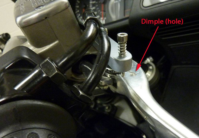
Tony has followed a different path designing his handbrake. Instead of attempting to keep the front brake applied by sticking something into the far inboard end of the brake lever, he's designed a device that fits into a small dimple (hole) drilled into the top of the front handbrake lever. The general principle is the same, though: To use it, you squeeze the front brake lever in the normal way, then press down on the top of a spring-loaded pin that is captive in the end of a bar mounted above the brake lever. This inserts the pin into the hole in the top of the lever. The pin is spring-loaded to pop up out of the hole in the brake lever, and the hole is larger than the pin. Thus, any further squeezing of the brake lever once the parking brake is applied will cause the pin to pop up and the handbrake to release. It works well.
Tony provides a complete set of illustrated instructions with the kit (the instructions are also available at his website, click here). I'm not going to attempt to duplicate his instructions here, but rather to provide a general overview of how the thing works, and what is involved in installing it.
First, you remove the front brake lever, and using the existing Honda bolt and the washers, nut, and drilling template that Tony provides, you mount the drilling template onto the top of the handbrake lever. The smaller hole on on the drilling template, on the right side of the picture below, shows where the hole will be drilled in the handbrake lever.
Drilling Template Mounted
The hole will be drilled more or less at the outboard end of the arrow embossed on the lever.
Hole Partially Drilled
I had to sneak a peek. The handgrip is 18 mm thick at this point, the hole will only be 5 mm deep
Hole Drilled, Everything Re-Installed
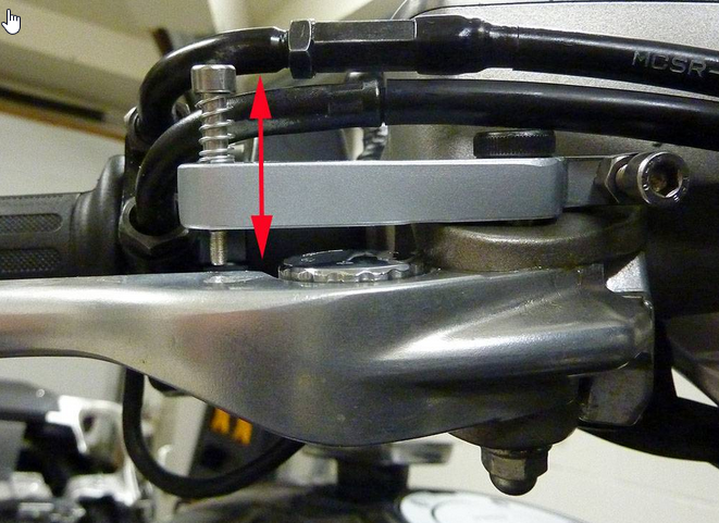
How it works (pin movement up and down into hole)
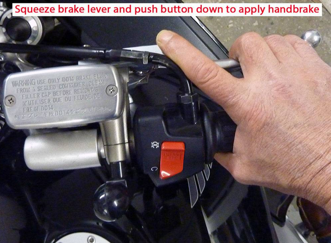
How it is Applied
To release it, just slightly squeeze the brake lever in the normal manner, no need to touch the parking brake, it will pop up.
What it looks like when Applied
I was a bit apprehensive about the idea of drilling a hole partway into the front brake lever. But, after thinking about it for a bit, I realized that the hole (a dimple, actually) is only 4 mm deep, and the handbrake lever is 18 mm thick at the point where the hole gets placed. Besides, Honda has already drilled a much larger hole completely through the handbrake lever casting - up where it pivots to apply the brake (where the bolt goes) - and I have heard no reports of the casting breaking where Honda put their hole.
I was also kind of apprehensive about my limited skill drilling holes in metal, but the task was made pretty simple by the template and drill bit that Tony provides. The only thing I had to pay attention to was making sure I did not drill any deeper than the 4 to 6 mm specified (final depth of my hole was 4.5 mm).
All told, it took about 30 minutes to carry out this installation, and 10 minutes of that time was fetching the drill and then putting the drill away.
The Pendle Parking Brake for the ST 1300 works as well as the original Middleton design for the ST 1100. I'm very happy with it, and recommend it without reservation to others. Be aware that it is only intended to be used when the rider is astride the motorcycle - in other words, if you want to park your bike on a hill using the side-stand, you put the engine in gear as you normally would. This handbrake would hold the moto parked on a hill, but if anyone bumps the front brake lever, the handbrake will instantly release, as it is designed to do.
The only addition I would make to the otherwise excellent instructions that Tony provides with the kit is to suggest that after installing everything, you apply a little bit of oil to the spring-loaded pin that goes up and down, to ensure that it extends and retracts easily and without any friction. It would be nice if the button on top of the spring-loaded pin was bigger... I'm going to keep my eyes open for something that I can put over it to provide a larger surface to push on. But, there is no problem operating the pin as it is now.
Tony sells these parking brakes on eBay for ₤30 ( about $50 US Dollars), shipping included. You'll have to go on eBay and search for "Pendle Parking Brake" to find it. His website, which contains information and installation instructions, is here. I believe that he sells a similar device for the ST 1100, but I am not familiar with that device.
~~~
Ooops, I forgot to mention that the amount of pressure that the handbrake exerts when applied can be adjusted using a small set-screw at the inboard end of the lever. Because this facility for adjustment is provided, fore and aft placement of the hole (when drilling it) is not critical. I chose to try and center the hole front to back in the brake lever, I think that position minimizes the risk of any cracks propagating in the casting as a result of the hole being drilled.
The adjustment set-screw allows for brake lever position to be changed using the chrome dial on the brake lever without any loss of efficiency of the parking brake.
Adjustment Set-Screw
~~~
Thank You again for your contribution Michael Moore, STOC #2636
#10
ST1300 Archive of Wisdom / Common Torque Values and Wrenc...
Last post by KoTAOW - August 10, 2018, 09:47:54 AMContributed by Ray Antasek, STOC #XXX.
~~~
Direct link to file: https://www.dropbox.com/s/goqdogvxtw62ocw/ST1300%20Torque.pdf?dl=0
~~~
Thank You again for your contribution Ray Antasek, STOC #XXX
~~~
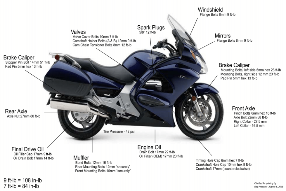
Common Torque Values and Wrench Sizes ( ST1300 )
Direct link to file: https://www.dropbox.com/s/goqdogvxtw62ocw/ST1300%20Torque.pdf?dl=0
~~~
Thank You again for your contribution Ray Antasek, STOC #XXX