- Welcome to ST-Riders - The liST.

The Original ST1100/ST1300 Forum
Recent posts
#21
ST1100 Archive of Wisdom / Re: External Auxiliary Fuel Pu...
Last post by KoTAOW - March 08, 2017, 01:14:57 PMExternal Auxiliary Fuel Pump ( ST1100 ) - Part 2
~~~
Additional comments by Raouf Wilson:
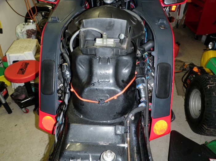
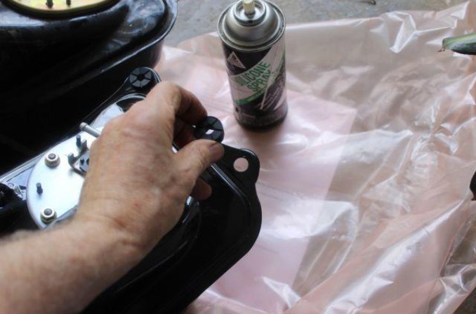
Okay some final pictures of the setup I have now.
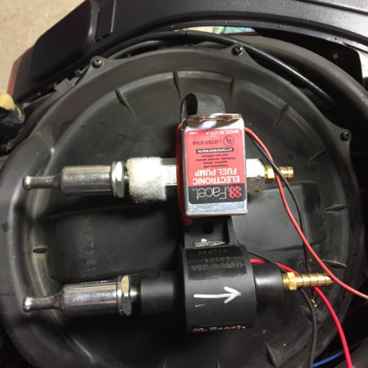
1. The set up.
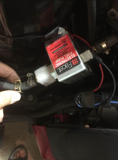
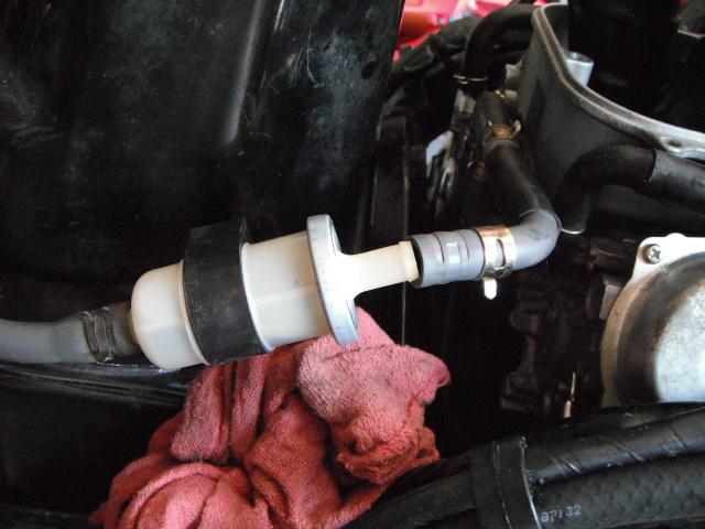
2. Facet model 60304 with Facet Fuel filter.
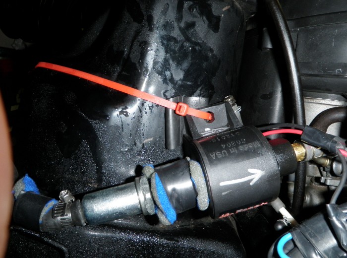
3. OEM clamp using existing carb fuel line and brass 5/8 hose barb in Facet.
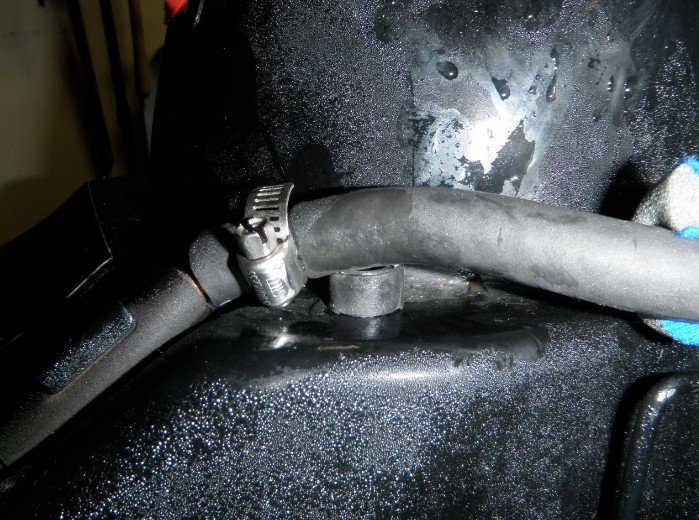
4. Rubber shim to keep the hose clamp from touching tank.
5. I used the OEM fuel filter but too many clamps and too long and tough to fit plastic back on.
6. Zip ties are your friend, red of course. Go under the seat hook.
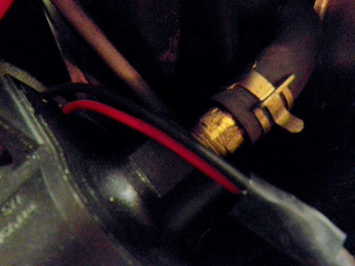
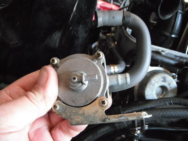
Keep the OEM Vacuum bypass set up for later use, when you finally buy a proper OEM pump and be a cheap ass like me. Okay I bought a used one or two that I will carry too.
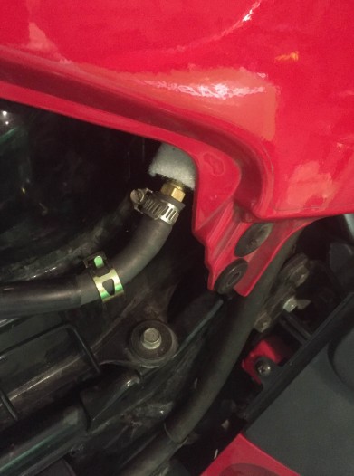
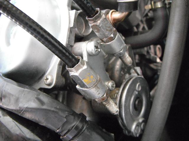
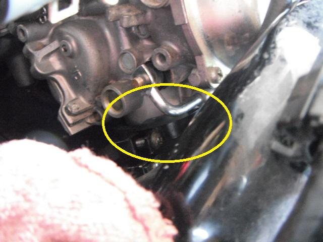
See all those extra hose clamps and OEM Fuel filter. Why does the bypass only have 1 screw. You all know that there are 2 holding it to the air filter housing.
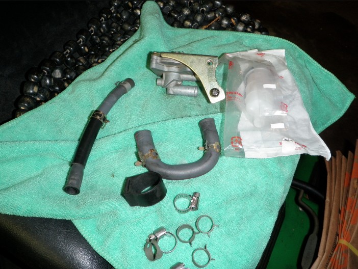
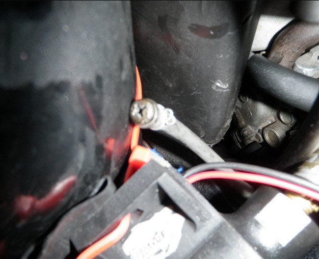
Okay here is where the missing screw went. I figured this out while I was looking to see what I could find to fit that, a golf tee would be good too. That vacuum hose needs to be blocked, since the by pass valve has been by passed..

Here is what the pump sounds like. It was scary to hear this the first time from such a small pump.
~~~
Thank You again for your contribution Raouf Wilson, STOC #6136
#22
ST1100 Archive of Wisdom / External Auxiliary Fuel Pump (...
Last post by KoTAOW - March 08, 2017, 01:13:48 PMSubmitted by Raouf Wilson, STOC #6136
~~~
Original "Help, Save Me" thread (Link)
~~~
I had the fuel pump strand me on I-70 about an hour West of Grand Junction during WeSToc. Thanks to the liST, Dave Nichols sent me his Facet fuel pump and fitted it with the plumbing and wires and shipped it to me overnight so I can get set and hit the road home. Just in case there was a problem, Adam Frymoyer sent me the pump out of Will's bike, which arrived the next day, which was Friday morning for the journey home. I am grateful to the kind PMs from Dave Speer, Jim Medak, and support on my "Help, Save Me" thread and Jim Vick going to see if the pump was at Apex. Awesome support
So here is the summary:
The Facet 40178 (Link) got me home, it used a bit more fuel than average, I average 46 mpg in everyday type riding, since I got the bike (I keep a mileage log). OEM pump to WeSToc high was 54 mpg and low was 45 mpg.
Trip home with Facet, high was 45 mpg and low was 40.7 mpg.
I was tense as anything for the first few hours, especially through Vale, where it got windy and wasn't sure if it was buffeting or the fuel starvation. I couldn't smell fuel which was a good sign, and filled up as soon as I hit half tank.
The Facet pump makes a thumping sound, which is apparently normal. I never heard the sound until I got home, so thought the pump was toast, but I emailed Facet and they said it was normal. I thought it odd that I hadn't heart it before, then I realized there were a couple of reasons; when I installed it, John Parker was working on his bike beside me and revving it, and I was ecstatic that my bike was now working and wouldn't have heard anything except joy! When I turn the key on, the pump starts thumping, but of course I had my earplugs in, so couldn't hear that sound. It was only at home when in the quiet garage, when I turn on the key that I heard it, and couldn't figure out what it was.
The Facet pump was hooked up straight from the fuel line coming out of the tank, direct to the carburetor hose, the fuel vacuum shutoff valve was removed, and I wired the pump to my Centech II auxiliary fuse block which I have under the headlight. So the pump would run when ignition was on. I left the OEM pump wired as is. Before I installed the Facet, my bike did fire up on the OEM pump, but I wasn't going to take a chance. I also didn't have any fuel filter attached. When I got home I found the Facet fuel filter that screwed right into the pump and worked well.
Fast Forward to October, 2016.....
I didn't like the idea of the extra pressure this pump puts out (2.0-3.5) plus I wanted to use a switch to turn it off and on so I can see if my OEM pump still works and keep the aux pump as standby. This model pump has a positive shut off valve, so no power, no flow and would block the OEM pump.
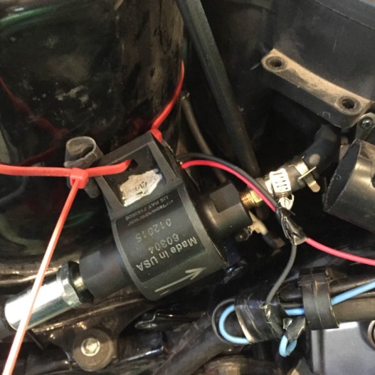
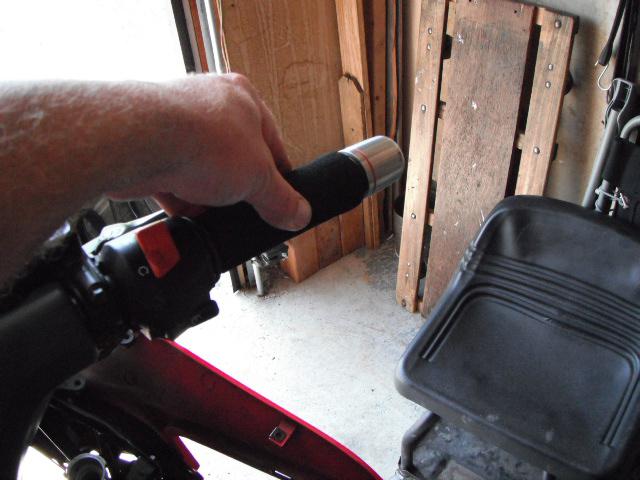
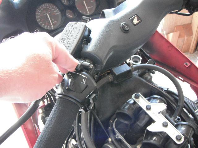
So I ordered the: Facet 60304 Posi-Flo Pump (Link) with no shutoff valve. So wired it using one of the Police Right hand switches, so I can turn off and on and see how OEM pump works. Of course no time for a long test drive until mid November when it was too good a day to go to work, managed a 250 mile ride to test the Facet pump and the mileage was 45.5 mpg. Of course one ride isn't going to prove much, but I did try to ride my usual places to get an idea.
Once the riding season starts for 2017, I will get more numbers, and then I will turn it off and see how the OEM does.
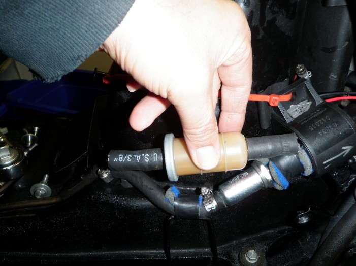
The most important thing to note is you need a 3/8 hose barb. I cannot find one here, only 5/16, which even with a hose clamp, will leak while connected to the carburetor hose. I didn't want to cut any hoses or mess with the OEM setup, so it can go back to stock at any time. The Facet fuel filter fits great to the fuel tank hose, which is smaller than the carb hose. I also didn't want to cut that OEM fuel tank hose, so bought a fuel hose that I can butcher to custom.
This would be something to consider adding to the emergency kit as it doesn't cost too much and take up too much room. Estimated cost: $36.50 ( 2017 )
Here are some pics:
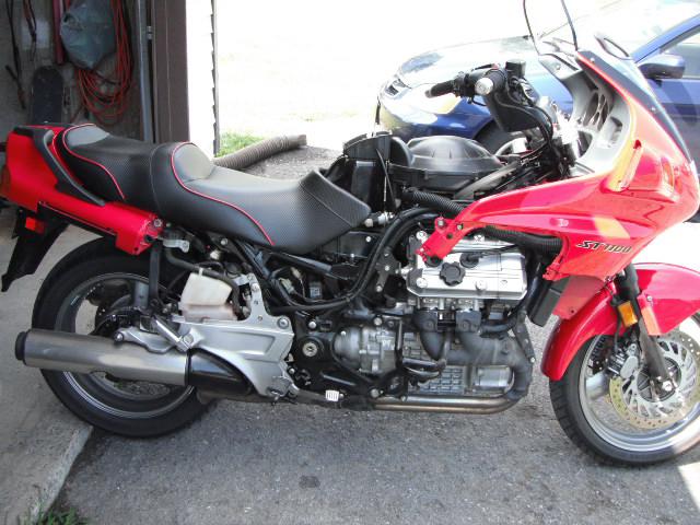
1. Setup to get me home no fuel filter
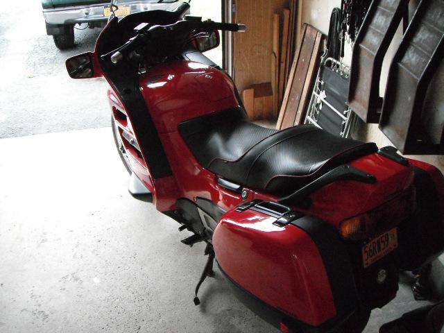
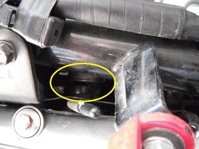
2. How it buttons up, it is tight under there.
3. Comparing old one, red cover and new one, more plastic feeling but still heavy
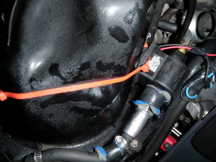
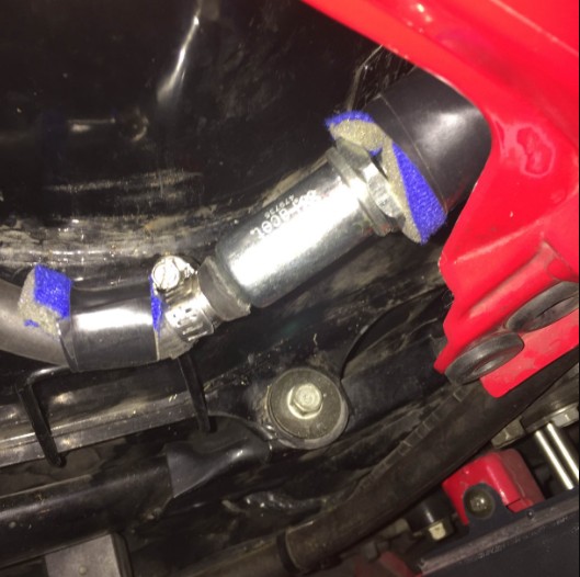
4. Initial set up, with 5/16 fitting, I was smelling gas, no good.
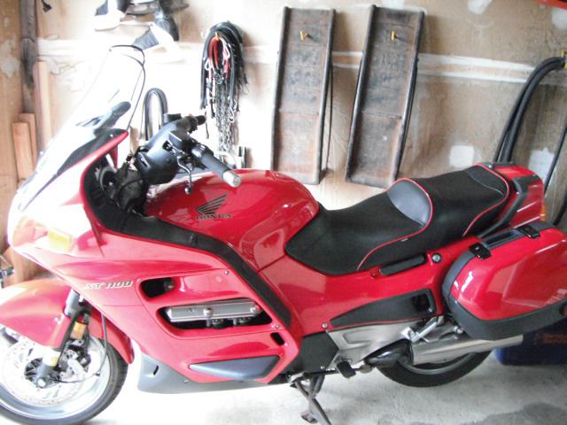
5. How it looks all done, some foam pads to keep it from vibrating against the tupperware.
~~~
Additional Comments by Raouf Wilson:
Jeff Nichols brings up a good point in suggestion that the wires should be hooked up to the OEM pump wires so that the tip over shutoff circuit can be utilized. I think this would be wise for a long term install.
Additional question by Tom Melnik:
I was thinking the same thing after reading your write up, why not just wire it into the existing pump wires.
Does the OEM pump have to operate at the same time as the external pump?
Can the external pump pull fuel out of the tank with the OEM off?
Additional comment by Raouf Wilson:
The aux fuel pump will operate off the OEM pump wires, I tried when I got home.
The aux fuel pump will also operate with the OEM pump not turned on. I had them both working as I wasn't sure if the OEM pump was off, it would have restricted the flow in any way. Once home I disconnected the wires to the OEM pump and the aux worked just fine.
Right now my set up is to have the aux fuel pump turned on and off with a switch, and have the OEM running. My next change will be to run the aux fuel pump off the OEM circuit for the shutoff operation. Right now if something happened and the ignition key was still on, the aux pump would just be pushing fuel out.
Ideally, I would also like to put the vacuum shut off valve back, but there is such little room for aux pump as it is, I may just have to live with that set up.
~~~
External Auxiliary Fuel Pump ( ST1100 )
Original "Help, Save Me" thread (Link)
~~~
I had the fuel pump strand me on I-70 about an hour West of Grand Junction during WeSToc. Thanks to the liST, Dave Nichols sent me his Facet fuel pump and fitted it with the plumbing and wires and shipped it to me overnight so I can get set and hit the road home. Just in case there was a problem, Adam Frymoyer sent me the pump out of Will's bike, which arrived the next day, which was Friday morning for the journey home. I am grateful to the kind PMs from Dave Speer, Jim Medak, and support on my "Help, Save Me" thread and Jim Vick going to see if the pump was at Apex. Awesome support
So here is the summary:
The Facet 40178 (Link) got me home, it used a bit more fuel than average, I average 46 mpg in everyday type riding, since I got the bike (I keep a mileage log). OEM pump to WeSToc high was 54 mpg and low was 45 mpg.
Trip home with Facet, high was 45 mpg and low was 40.7 mpg.
I was tense as anything for the first few hours, especially through Vale, where it got windy and wasn't sure if it was buffeting or the fuel starvation. I couldn't smell fuel which was a good sign, and filled up as soon as I hit half tank.
The Facet pump makes a thumping sound, which is apparently normal. I never heard the sound until I got home, so thought the pump was toast, but I emailed Facet and they said it was normal. I thought it odd that I hadn't heart it before, then I realized there were a couple of reasons; when I installed it, John Parker was working on his bike beside me and revving it, and I was ecstatic that my bike was now working and wouldn't have heard anything except joy! When I turn the key on, the pump starts thumping, but of course I had my earplugs in, so couldn't hear that sound. It was only at home when in the quiet garage, when I turn on the key that I heard it, and couldn't figure out what it was.
The Facet pump was hooked up straight from the fuel line coming out of the tank, direct to the carburetor hose, the fuel vacuum shutoff valve was removed, and I wired the pump to my Centech II auxiliary fuse block which I have under the headlight. So the pump would run when ignition was on. I left the OEM pump wired as is. Before I installed the Facet, my bike did fire up on the OEM pump, but I wasn't going to take a chance. I also didn't have any fuel filter attached. When I got home I found the Facet fuel filter that screwed right into the pump and worked well.
Fast Forward to October, 2016.....
I didn't like the idea of the extra pressure this pump puts out (2.0-3.5) plus I wanted to use a switch to turn it off and on so I can see if my OEM pump still works and keep the aux pump as standby. This model pump has a positive shut off valve, so no power, no flow and would block the OEM pump.
So I ordered the: Facet 60304 Posi-Flo Pump (Link) with no shutoff valve. So wired it using one of the Police Right hand switches, so I can turn off and on and see how OEM pump works. Of course no time for a long test drive until mid November when it was too good a day to go to work, managed a 250 mile ride to test the Facet pump and the mileage was 45.5 mpg. Of course one ride isn't going to prove much, but I did try to ride my usual places to get an idea.
Once the riding season starts for 2017, I will get more numbers, and then I will turn it off and see how the OEM does.
The most important thing to note is you need a 3/8 hose barb. I cannot find one here, only 5/16, which even with a hose clamp, will leak while connected to the carburetor hose. I didn't want to cut any hoses or mess with the OEM setup, so it can go back to stock at any time. The Facet fuel filter fits great to the fuel tank hose, which is smaller than the carb hose. I also didn't want to cut that OEM fuel tank hose, so bought a fuel hose that I can butcher to custom.
This would be something to consider adding to the emergency kit as it doesn't cost too much and take up too much room. Estimated cost: $36.50 ( 2017 )
Here are some pics:
1. Setup to get me home no fuel filter
2. How it buttons up, it is tight under there.
3. Comparing old one, red cover and new one, more plastic feeling but still heavy
4. Initial set up, with 5/16 fitting, I was smelling gas, no good.
5. How it looks all done, some foam pads to keep it from vibrating against the tupperware.
~~~
Additional Comments by Raouf Wilson:
Jeff Nichols brings up a good point in suggestion that the wires should be hooked up to the OEM pump wires so that the tip over shutoff circuit can be utilized. I think this would be wise for a long term install.
Additional question by Tom Melnik:
I was thinking the same thing after reading your write up, why not just wire it into the existing pump wires.
Does the OEM pump have to operate at the same time as the external pump?
Can the external pump pull fuel out of the tank with the OEM off?
Additional comment by Raouf Wilson:
The aux fuel pump will operate off the OEM pump wires, I tried when I got home.
The aux fuel pump will also operate with the OEM pump not turned on. I had them both working as I wasn't sure if the OEM pump was off, it would have restricted the flow in any way. Once home I disconnected the wires to the OEM pump and the aux worked just fine.
Right now my set up is to have the aux fuel pump turned on and off with a switch, and have the OEM running. My next change will be to run the aux fuel pump off the OEM circuit for the shutoff operation. Right now if something happened and the ignition key was still on, the aux pump would just be pushing fuel out.
Ideally, I would also like to put the vacuum shut off valve back, but there is such little room for aux pump as it is, I may just have to live with that set up.
#23
ST1100 Archive of Wisdom / Re: Fork Seal R&R Tips ( ST110...
Last post by John OoSTerhuis - November 14, 2016, 09:00:03 PMDamper rod holding tools.
#24
ST1300 Archive of Wisdom / Re: Lower Fuel Tank Replacemen...
Last post by KoTAOW - June 11, 2015, 07:17:52 PMLower Fuel Tank Replacement ( ST1300 ) - Part 2
*************************************************************************************************
INSTALLATION OF REPLACEMENT TANK
Installation basically consists of doing everything in reverse. I do have a couple of notes
on this though:
NOTE 1: You will have to reuse the rubber grommets from your old tank. These are
located in the tank mounting holes. They just pull right out. To put them in the new
tank, just spray a little silicone oil on them, do a bit of squeezing and pressing, and
they'll pop right in.
NOTE 2: I put my new fuel pump in the replacement tank before I slipped it into
the bike. To do this I just put the pump in and lightly finger tightened the nuts. I did
this because I did not want to fight the wiring harness that hangs over the left rear
corner of the tank when it is installed.
NOTE 3: VERY IMPORTANT. When you get the lower tank back in and fastened,
the next step is to torque down the fuel pump nuts on the new lower tank. There is a
definite sequence and torque value that has to be followed when tightening these
nuts. This sequence differs for '03 and post '03 ST13 models.
The fuel pump tightening sequence diagram is located on pg 5-56 & 5-57 of the '05
SM. It's also located on 1-15 '05 SM where it also shows the torque values for the
various fasteners. If you don't have a SM, just google for it under the subject
"ST1300 fuel pump replacement" or ask on an online, ST1300 forum.
Before I even slipped the tank back in, I wrote the correct sequence number on the
top of the fuel pump by each nut using a black felt tip marker. Unfortunately I did
not take a picture of it.
After the tank was installed and every thing else buttoned up, I first finger
tightened each nut as much as possible in sequence. I then worked in sequence
around the pump in steps, tightening just a little during one round, then a bit more
in the succeeding rounds using a torque wrench until I reached recommended
torque of 12 NM <9 ft-lbs> seen on the above pages.
NOTE 4: I used new washers on the large banjo fitting that attaches the outgoing
gas line to the fuel pump. Not sure it's needed but they are cheap and I wanted to
minimize the possibility of leaks so that I'd have to do this job only once!
*************************************************************************************************
UPPER FUEL TANK REPLACEMENT (pg 5-60 '05 SM & 5-59 '03 SM):
I won't go into detail on this but I do have a few notes on this:
NOTE 1. Honda recommends to use a new fuel joint hose (connects upper to lower
tank) and clips. I followed their advice.
** NOTE 2. Check for leaks. Once the tank is on and completely hooked up, slowly
pour in gas in steps and check for leaks. Raise the upper tank occasionally to check
for leaks at the fuel joint hose beneath the tank. I looked at http://stwiki.notonthe.net/twiki/bin/view/ST13/FuelGauge to
get a feel for how much gas to put in to fill the lower tank plus a little bit in the connecting hose. After a
brief check, I proceeded in a step wise manner putting more and more gas and checking for leaks. I did this in steps
because the more fuel that's in the top tank, the higher the pressure in the joint hose and on the fuel pump seal.
After filling the tank with a bit over 5 gallons, let it sit overnight before starting to make sure there are no small leaks.
*************************************************************************************************
Final Note - no leaks, the bike ran well, all was good.
That's all folks. Hopefully you'll never have to replace a lower fuel tank.
~~~
Thank You again for your contribution Mick McHam, STOC #1134
#25
ST1300 Archive of Wisdom / Lower Fuel Tank Replacement ( ...
Last post by KoTAOW - June 11, 2015, 07:16:40 PMSubmitted by Mick McHam, STOC #1134
Original article in PDF here: Lower Fuel Tank Replacement Steps - Rev c
Mick: I had to replace my lower fuel tank about 6 months after I bought my ST1300 in 2012. It was way more involved than I would have thought and it took a good deal of time. Because I am apparently one of the very few ST1300 owners who've had to do this job, I did a "how-to" write up of it and put it in PDF form (attached). Lots of pictures to help guide you through the process.
~~~
PRELIMINARIES:
This work was performed on a 2005 model ST1300.
This "how to" guide is intended as a compliment to the ST1300 Service Manual (SM). If you don't have a manual, get hold of a copy. There are some pictures and diagrams in the manual that would be helpful and some that you will need. At the very least, you'll need it for steps such as upper tank removal & installation (which I don’t cover here), double checking torque values, and especially the fuel pump tightening sequence for your year model ST. Since those sequence diagrams are probably copyrighted, I did not include them.
The instructions below are laid out in sequence from beginning to end saving you the time of having to hop back and forth around the ST1300 SM. My step numbering system reflects the "nesting" that resulted from having been referred by the SM to multiple pages to perform subordinate steps.
Although I do mention the upper tank, this procedure basically starts with the upper tank already off.
As much as possible, I reference page numbers in the SM so that you can double check or look for clarification. Because I have both, I've referenced page #'s for the 2005 ST1300 and the 2003 ST1300. There are differences.
I've listed torque values for use in reassembly.
Tips & Notes will be in green text.
- it is important to read each step's notes before proceeding.
Steps are in red text.
*************************************************************************************************
Before Beginning...Words of Wisdom
1. Take pictures, lots & lots of pictures, from all different angles before you perform a step. These are absolutely invaluable when putting everything back together. Remember that every hose and every wire has to be connected back up AND routed exactly like it was from the factory. I took a bunch of pictures but wish I'd have taken more.
2. Because there are so many fasteners and parts involved in this procedure, put fasteners in a labeled, zip lock bag for each item. I even taped these bags to the part they go to when possible, such as the cowlings, fenders, etc. just to keep things as organized as possible.
3. Make ABSOLUTELY sure that there is no gas in the upper tank or connecting hoses & lines before removing the upper tank. To accomplish this, I ran the bike until there was one blinking bar on the gas gauge as indicated in the article at this link:http://stwiki.notonthe.net/twiki/bin/view/ST13/FuelGauge
*************************************************************************************************
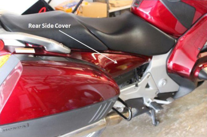
1. Remove the panniers and rear side covers. (pg 2-6, '05 & '03 SM)
2. Remove the upper tank after making sure there is no gas in the tank or lines.
Since most folks on this site have removed their upper tanks, I'll not go into the details
of removal. If you've never removed the upper tank before, see pg 5-57 '05 SM (p 5-56
'03 SM) for removal, & 5-60 '05 SM (5-59 '03 SM) for installation.
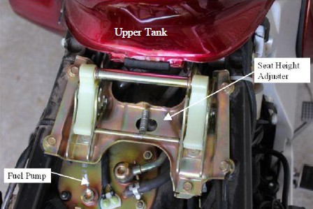
3. Remove the seat height adjuster.
NOTE: When removing the seat height adjuster, be sure and put rags in open
spaces where bolts could fall. This tip goes for any situation where bolts might fall
and be trapped in nether regions of the bike or dropped on the ground and roll into
hiding places.
3. Remove the seat rail (pg 2-22 in the '05 service manual(SM) & 2-19 in the '03 SM).
STEPS for rail removal:
A.Remove rear fender "B" (pg 2-9 '05 & '03 SM). This is the entire fender, not just
the one that holds the license plate. It sounds like a simple task but there is a lot to it!
STEPS for Rear Fender "B" removal:
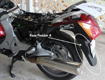
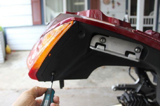
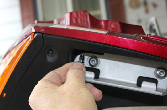
1a. Remove rear fender "A". This is the one that holds the license plate. (pg 2-8 in
'05 & '03 SM). There are four allen bolts to be loosened. Two on the outside facing to the rear and two underneath.
2a. Remove the rear wheel. Again, I'll not go into detail here since most have done
this many times. If you've never done it, see pg 16-6 of the '05 SM & 16-5 of the '03 SM.
NOTE: Torque values for use when remounting the rear wheel:
Muffler mounting bolts 17 NM <12 ft-lbs> (pg 2-4 '05 SM)
Muffler Band Bolts 22 NM <16 ft-lbs> (pg 16-13 & 2-20 '05 SM)
Caliper Stopper Bolt 69 NM <51 ft-lbs> (pg 16-12 '05 SM)
Rear Axle Nut 108 NM <80 ft-lbs> (pg. 16-13 '05 SM)
3a. Remove the battery (pg 19-5 in the '05 & '03 SM).
STEPS:
I. Remove fuse holder from the battery cover (see diagram pg 19-5 '05 SM)
II. Remove battery cover by releasing the tab from the rear fender groove and two hooks from the two tabs on the rear fender.
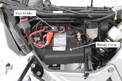
III. Disconnect negative then positive battery cable then remove battery.
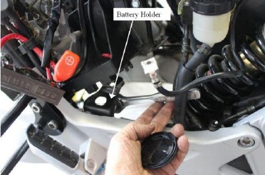
IV. Remove the metal battery holder (support bracket)
4a. Remove Rear Cowl (pg. 2-7 '05 & '03 SM)
STEPS:
I. Remove the Grab Rail Center Cover by removing the 4 bolts, collars & nuts.
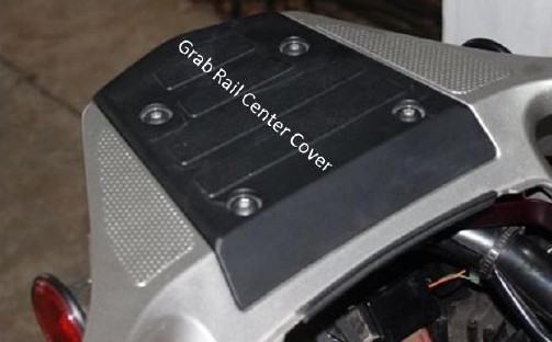
NOTE 1: Watch out for those collars & nuts! They will drop and go bouncing on the concrete and
come to rest in places never to be found!
NOTE 2:Torque values for reassembly. I used the standard for this bolt's size of 10 NM <7 ft-lbs> .
These standard values can be seen on pg 1-12 of the'05 SM. The size is that of the threaded part of the bolt, not the head size.
II. Remove the rear grab rail (pg 2-7 in '05 & '03 SM)
STEPS:
Remove the seat lock by removing the rubber strap and the bolt holding the locking mechanism down.
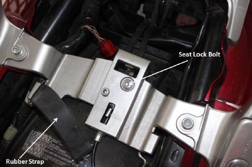
Remove the 4 bolts and washers that attach the grab rail.
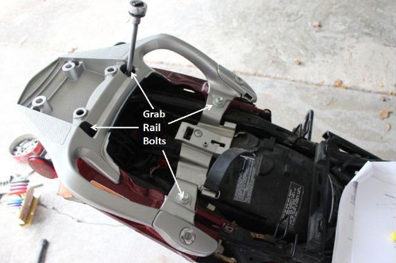
NOTE: Torque for reassembly. I used the 22 NM (16 ft-lbs)from the
standard torque value chart.
- Release the seat lock cable from the groove & remove the rear grab rail.
III. Disconnect and remove the rear cowl (pg 2-8, '05 & '03 SM)
STEPS:
- Remove the 4 screws, 2 socket bolts & 2 trim clips from the cowl
NOTE: I have in my notes that I did not see or work with the "2 socket
bolts" and that the cowl came off just fine.
- Remove the rear cowl and disconnect the rear turn signal 2 pin connectors &
tail/brake light 3 pin connectors <Honda wording>.
NOTE: I chose to just unscrew the bulb holders from the cowling
instead. I then wrapped and taped bubble wrap around the bulbs to protect them.
- Disconnect white plug on the seat rail near the ECU
- Release the band that secures the ABS control unit and ECM. Tape the whole mess to the back of the seat rail.
NOTE: Not totally sure this step didn't come after step 6a. My notes are unclear on this.
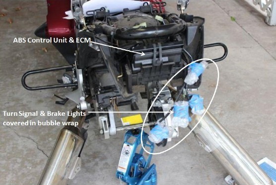
NOTE 2: The scissors jack in the above picture above was NOT touching the axle as I did not want to bend it. It was about 1/2" away
from the axle and was there just in case something were to happen to cause the rear end to tip down. Very unlikely but thought I'd be cautious.
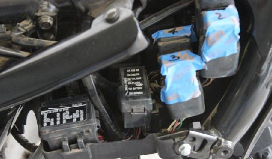
5a. Remove the relays & fuse boxes from the tabs on the rear fender (pg 2-9, '05 & '03 SM & pg. 1-45 '05 SM)
NOTE 1: I put tape on the top of each relay and numbered them. These numbers were then recorded on a copy of the relay cluster
found on pg. 1-45 of the '05 SM & pg. 1-42 in the '03 SM.
NOTE 2: I have in my notes that there are release tabs on the fuse boxes.
6a. Remove the saddlebag holders. (diagram pg 2-9 '05 & '03 SM)
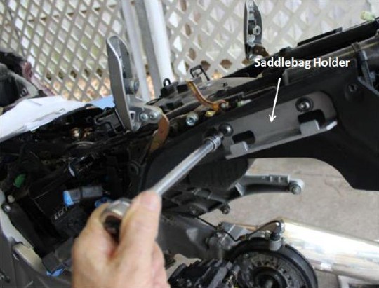
NOTE: Torque for reassembly of these saddle bag holder bolts is 26 NM <20 ft-lbs> (pg 1-15, '05 & '03 SM,
under "Frame Body Panels/Exhaust System)
7a. Remove the remaining bolts from the rear fender & pull the fender out
(diagram, pg 2-9 '05 & '03SM). See notes below before proceeding.
NOTE 1: There is a bolt to take of off near the relay shelf (see silver bolt, bottom right in the picture in step 5a.). I think
there might have been one on the right side (didn't take enough pictures or notes!!).
NOTE 2: There are all kinds of things in the way when trying to pull the fender out the rear of the bike. I had to back off the
lower seat rail socket bolts (pg 2-23 '05 SM & 2-20 '03 SM) until the ends were flush with the frame. These are the
bolts that your Bydawg tip-over bars attach near the passenger foot pegs. I also had to loosen the bolt that goes to the
remote shock adjustment bracket where it attaches to the frame (pg 2-22 '05 SM & 2-19 '03 SM).
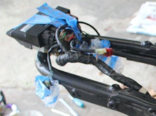
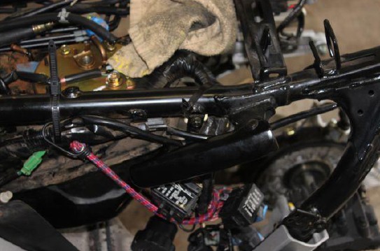
NOTE 3: At this point you've got quite a gaggle of relays and wires hanging after they were removed from the rear
fender in step 5a. These could get in your way when you try to pull the fender back and/or tank out. I used a
bungee cord and wrapped the whole mess up into a bundle and pulled it out of the way. Unsure I if I
did this before the fender removal or before the tank removal. (see pic below)
NOTE 4: I had to let the rear brake caliper hang free before the fender would come out.
NOTE 5: Pulling the rear fender out requires that the fender be squeezed and jiggled around quite a bit to get it out.
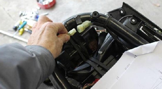
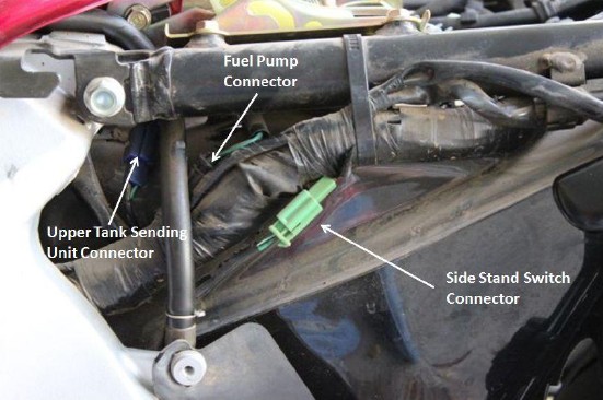
B. Disconnect the green, side stand switch 2-pin connector and the black fuel pump just underneath the upper seat rail near the front tank. The blue connector also located in this area should already be disconnected from having removed the upper tank.
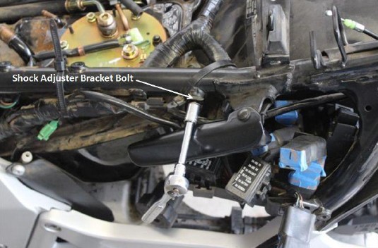
C. Disconnect the shock adjuster bracket from the seat rail (pg 2-22 '05 SM & 2-19 '03 SM).
D. Remove the starter relay switch from the seat rail (pg 2-22 '05 SM & 2-20 '03 SM).
This relay is rearward of the battery compartment.
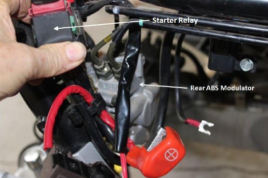
E. Remove the bolts and the rear ABS modulator <Honda's wording> (pg 2-22 '05 SM & 2-20 '03 SM).
*** See note below before proceeding ***
***NOTE: This step is the only place where I almost got into trouble. I took the above (step 7) to mean to disconnect the modulator from the bracket then remove the ABS modulator from the bike. This would have entailed disconnecting the four brake lines that feed into it. Made sense because when the modulator was separated from its bracket, it was suspended at the end of long, small diameter, metal brake fluid pipes. It looked like the weight of the modulator could cause the pipes to bend.
** DO NOT REMOVE THE BRAKE LINES FROM THE ABS MODULATOR**
I disconnected one of the lines then went to remove a second. I did not have a set of
flare nut wrenches so I just used an open end 10mm wrench. When I tried to
disconnect that second line, I managed to round part of the nut. It was like someone
put it on with an impact wrench! I looked at the SM and it turns out these nuts are
torqued down to 34 NM! No wonder I was having such a difficult time.
At this point, still not knowing that I had misinterpreted the instructions, I said to
heck with it, there's no way I'm going to be able to remove those lines so I decided to
just leave them connected and see how it went.
When I went to reconnect the one flare nut I managed to remove, I encountered
great difficulty because the long, finely threaded connector wanted to cross thread.
Hard to describe but I couldn't get the modulator in the right position because the
other 3 lines kept the modulator in a slightly off kilter position. After many
attempts, I finally got it back on and breathed a huge sigh of relief.
To prevent damage to the metal brake lines, I made a cardboard support for the
modulator which can be seen in this picture:
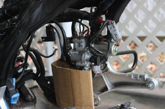
NOTE: Torque for ABS Modulator mounting bolts for reassembly = 12 NM <9 ftlbs>. (pg 1-12 '05 SM)
F. Remove the 4 lower fuel tank mounting bolts & washers (p 2-22 '05 SM & 2-20 '03 SM)
No pictures but you can see them in the SM pictures at the pages noted above. The location of these bolts are unmistakable at this point.
NOTE: for reassembly, the four tank mounting bolts are torqued at 12 NM <9 ft-lbs>. (p 1-12 '05 SM)
G. Remove the seat rail lower mounting socket bolts (pg 2-23 '05 SM & 2-20 '03 SM). These are the bolts that the affix the Bydawg tip-over bars if you have them.
NOTE: for reassembly, the bolts are torqued to 42 NM <31 ft-lbs>.

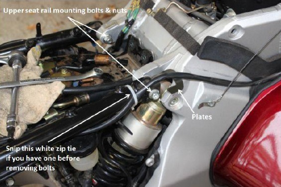
H. Remove the upper mounting nuts, plates & bolts then remove the seat rail
<Honda's wording> (p 2-23 '05 SM & 2-20 '03 SM). See pics in the SM.
*** IMPORTANT NOTE: ***
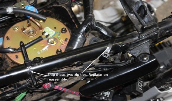
NOTE 1: I did NOT completely remove the seat rail as there is no need to do this
AND there were still things attached. What I did do was snip just the harness zip
ties near the lower tank (see pic below) so that I could just raise the rail out of the
way to enable to tank to slide back.
I also snipped the white zip tie seen in the photo. It secures the wire that plugs into
the OEM, auxiliary electrical socket mounted near the right fairing pocket. Take
note of how it runs if you have this wire.
NOTE 2: for reassembly, the upper rail flange bolt is torqued to 39 NM (29 ft-lbs). (pg 2-23 '05 SM)
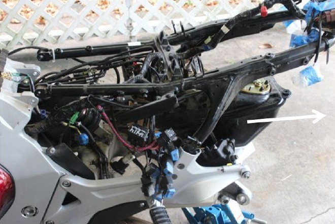
4. Remove the lower fuel tank
STEPS:
A. Be sure that the fuel pump electrical connector is disconnected as well as all hoses & lines.
B. Lift the seat rail up and slightly back, then slide the lower fuel tank out the back. You will have to jiggle it a bit where it
connects to the seat rail but it'll come out.
... out she comes:
*************************************************************************************************
Original article in PDF here: Lower Fuel Tank Replacement Steps - Rev c
Mick: I had to replace my lower fuel tank about 6 months after I bought my ST1300 in 2012. It was way more involved than I would have thought and it took a good deal of time. Because I am apparently one of the very few ST1300 owners who've had to do this job, I did a "how-to" write up of it and put it in PDF form (attached). Lots of pictures to help guide you through the process.
~~~
Lower Fuel Tank Replacement ( ST1300 ) - Part 1
PRELIMINARIES:
This work was performed on a 2005 model ST1300.
This "how to" guide is intended as a compliment to the ST1300 Service Manual (SM). If you don't have a manual, get hold of a copy. There are some pictures and diagrams in the manual that would be helpful and some that you will need. At the very least, you'll need it for steps such as upper tank removal & installation (which I don’t cover here), double checking torque values, and especially the fuel pump tightening sequence for your year model ST. Since those sequence diagrams are probably copyrighted, I did not include them.
The instructions below are laid out in sequence from beginning to end saving you the time of having to hop back and forth around the ST1300 SM. My step numbering system reflects the "nesting" that resulted from having been referred by the SM to multiple pages to perform subordinate steps.
Although I do mention the upper tank, this procedure basically starts with the upper tank already off.
As much as possible, I reference page numbers in the SM so that you can double check or look for clarification. Because I have both, I've referenced page #'s for the 2005 ST1300 and the 2003 ST1300. There are differences.
I've listed torque values for use in reassembly.
Tips & Notes will be in green text.
- it is important to read each step's notes before proceeding.
Steps are in red text.
*************************************************************************************************
Before Beginning...Words of Wisdom
1. Take pictures, lots & lots of pictures, from all different angles before you perform a step. These are absolutely invaluable when putting everything back together. Remember that every hose and every wire has to be connected back up AND routed exactly like it was from the factory. I took a bunch of pictures but wish I'd have taken more.
2. Because there are so many fasteners and parts involved in this procedure, put fasteners in a labeled, zip lock bag for each item. I even taped these bags to the part they go to when possible, such as the cowlings, fenders, etc. just to keep things as organized as possible.
3. Make ABSOLUTELY sure that there is no gas in the upper tank or connecting hoses & lines before removing the upper tank. To accomplish this, I ran the bike until there was one blinking bar on the gas gauge as indicated in the article at this link:http://stwiki.notonthe.net/twiki/bin/view/ST13/FuelGauge
*************************************************************************************************
BEGIN LOWER TANK REMOVAL PROCEDURE
1. Remove the panniers and rear side covers. (pg 2-6, '05 & '03 SM)
2. Remove the upper tank after making sure there is no gas in the tank or lines.
Since most folks on this site have removed their upper tanks, I'll not go into the details
of removal. If you've never removed the upper tank before, see pg 5-57 '05 SM (p 5-56
'03 SM) for removal, & 5-60 '05 SM (5-59 '03 SM) for installation.
3. Remove the seat height adjuster.
NOTE: When removing the seat height adjuster, be sure and put rags in open
spaces where bolts could fall. This tip goes for any situation where bolts might fall
and be trapped in nether regions of the bike or dropped on the ground and roll into
hiding places.
3. Remove the seat rail (pg 2-22 in the '05 service manual(SM) & 2-19 in the '03 SM).
STEPS for rail removal:
A.Remove rear fender "B" (pg 2-9 '05 & '03 SM). This is the entire fender, not just
the one that holds the license plate. It sounds like a simple task but there is a lot to it!
STEPS for Rear Fender "B" removal:
1a. Remove rear fender "A". This is the one that holds the license plate. (pg 2-8 in
'05 & '03 SM). There are four allen bolts to be loosened. Two on the outside facing to the rear and two underneath.
2a. Remove the rear wheel. Again, I'll not go into detail here since most have done
this many times. If you've never done it, see pg 16-6 of the '05 SM & 16-5 of the '03 SM.
NOTE: Torque values for use when remounting the rear wheel:
Muffler mounting bolts 17 NM <12 ft-lbs> (pg 2-4 '05 SM)
Muffler Band Bolts 22 NM <16 ft-lbs> (pg 16-13 & 2-20 '05 SM)
Caliper Stopper Bolt 69 NM <51 ft-lbs> (pg 16-12 '05 SM)
Rear Axle Nut 108 NM <80 ft-lbs> (pg. 16-13 '05 SM)
3a. Remove the battery (pg 19-5 in the '05 & '03 SM).
STEPS:
I. Remove fuse holder from the battery cover (see diagram pg 19-5 '05 SM)
II. Remove battery cover by releasing the tab from the rear fender groove and two hooks from the two tabs on the rear fender.
III. Disconnect negative then positive battery cable then remove battery.
IV. Remove the metal battery holder (support bracket)
4a. Remove Rear Cowl (pg. 2-7 '05 & '03 SM)
STEPS:
I. Remove the Grab Rail Center Cover by removing the 4 bolts, collars & nuts.
NOTE 1: Watch out for those collars & nuts! They will drop and go bouncing on the concrete and
come to rest in places never to be found!
NOTE 2:Torque values for reassembly. I used the standard for this bolt's size of 10 NM <7 ft-lbs> .
These standard values can be seen on pg 1-12 of the'05 SM. The size is that of the threaded part of the bolt, not the head size.
II. Remove the rear grab rail (pg 2-7 in '05 & '03 SM)
STEPS:
Remove the seat lock by removing the rubber strap and the bolt holding the locking mechanism down.
Remove the 4 bolts and washers that attach the grab rail.
NOTE: Torque for reassembly. I used the 22 NM (16 ft-lbs)from the
standard torque value chart.
- Release the seat lock cable from the groove & remove the rear grab rail.
III. Disconnect and remove the rear cowl (pg 2-8, '05 & '03 SM)
STEPS:
- Remove the 4 screws, 2 socket bolts & 2 trim clips from the cowl
NOTE: I have in my notes that I did not see or work with the "2 socket
bolts" and that the cowl came off just fine.
- Remove the rear cowl and disconnect the rear turn signal 2 pin connectors &
tail/brake light 3 pin connectors <Honda wording>.
NOTE: I chose to just unscrew the bulb holders from the cowling
instead. I then wrapped and taped bubble wrap around the bulbs to protect them.
- Disconnect white plug on the seat rail near the ECU
- Release the band that secures the ABS control unit and ECM. Tape the whole mess to the back of the seat rail.
NOTE: Not totally sure this step didn't come after step 6a. My notes are unclear on this.
NOTE 2: The scissors jack in the above picture above was NOT touching the axle as I did not want to bend it. It was about 1/2" away
from the axle and was there just in case something were to happen to cause the rear end to tip down. Very unlikely but thought I'd be cautious.
5a. Remove the relays & fuse boxes from the tabs on the rear fender (pg 2-9, '05 & '03 SM & pg. 1-45 '05 SM)
NOTE 1: I put tape on the top of each relay and numbered them. These numbers were then recorded on a copy of the relay cluster
found on pg. 1-45 of the '05 SM & pg. 1-42 in the '03 SM.
NOTE 2: I have in my notes that there are release tabs on the fuse boxes.
6a. Remove the saddlebag holders. (diagram pg 2-9 '05 & '03 SM)
NOTE: Torque for reassembly of these saddle bag holder bolts is 26 NM <20 ft-lbs> (pg 1-15, '05 & '03 SM,
under "Frame Body Panels/Exhaust System)
7a. Remove the remaining bolts from the rear fender & pull the fender out
(diagram, pg 2-9 '05 & '03SM). See notes below before proceeding.
NOTE 1: There is a bolt to take of off near the relay shelf (see silver bolt, bottom right in the picture in step 5a.). I think
there might have been one on the right side (didn't take enough pictures or notes!!).
NOTE 2: There are all kinds of things in the way when trying to pull the fender out the rear of the bike. I had to back off the
lower seat rail socket bolts (pg 2-23 '05 SM & 2-20 '03 SM) until the ends were flush with the frame. These are the
bolts that your Bydawg tip-over bars attach near the passenger foot pegs. I also had to loosen the bolt that goes to the
remote shock adjustment bracket where it attaches to the frame (pg 2-22 '05 SM & 2-19 '03 SM).
NOTE 3: At this point you've got quite a gaggle of relays and wires hanging after they were removed from the rear
fender in step 5a. These could get in your way when you try to pull the fender back and/or tank out. I used a
bungee cord and wrapped the whole mess up into a bundle and pulled it out of the way. Unsure I if I
did this before the fender removal or before the tank removal. (see pic below)
NOTE 4: I had to let the rear brake caliper hang free before the fender would come out.
NOTE 5: Pulling the rear fender out requires that the fender be squeezed and jiggled around quite a bit to get it out.
B. Disconnect the green, side stand switch 2-pin connector and the black fuel pump just underneath the upper seat rail near the front tank. The blue connector also located in this area should already be disconnected from having removed the upper tank.
C. Disconnect the shock adjuster bracket from the seat rail (pg 2-22 '05 SM & 2-19 '03 SM).
D. Remove the starter relay switch from the seat rail (pg 2-22 '05 SM & 2-20 '03 SM).
This relay is rearward of the battery compartment.
E. Remove the bolts and the rear ABS modulator <Honda's wording> (pg 2-22 '05 SM & 2-20 '03 SM).
*** See note below before proceeding ***
***NOTE: This step is the only place where I almost got into trouble. I took the above (step 7) to mean to disconnect the modulator from the bracket then remove the ABS modulator from the bike. This would have entailed disconnecting the four brake lines that feed into it. Made sense because when the modulator was separated from its bracket, it was suspended at the end of long, small diameter, metal brake fluid pipes. It looked like the weight of the modulator could cause the pipes to bend.
** DO NOT REMOVE THE BRAKE LINES FROM THE ABS MODULATOR**
I disconnected one of the lines then went to remove a second. I did not have a set of
flare nut wrenches so I just used an open end 10mm wrench. When I tried to
disconnect that second line, I managed to round part of the nut. It was like someone
put it on with an impact wrench! I looked at the SM and it turns out these nuts are
torqued down to 34 NM! No wonder I was having such a difficult time.
At this point, still not knowing that I had misinterpreted the instructions, I said to
heck with it, there's no way I'm going to be able to remove those lines so I decided to
just leave them connected and see how it went.
When I went to reconnect the one flare nut I managed to remove, I encountered
great difficulty because the long, finely threaded connector wanted to cross thread.
Hard to describe but I couldn't get the modulator in the right position because the
other 3 lines kept the modulator in a slightly off kilter position. After many
attempts, I finally got it back on and breathed a huge sigh of relief.
To prevent damage to the metal brake lines, I made a cardboard support for the
modulator which can be seen in this picture:
NOTE: Torque for ABS Modulator mounting bolts for reassembly = 12 NM <9 ftlbs>. (pg 1-12 '05 SM)
F. Remove the 4 lower fuel tank mounting bolts & washers (p 2-22 '05 SM & 2-20 '03 SM)
No pictures but you can see them in the SM pictures at the pages noted above. The location of these bolts are unmistakable at this point.
NOTE: for reassembly, the four tank mounting bolts are torqued at 12 NM <9 ft-lbs>. (p 1-12 '05 SM)
G. Remove the seat rail lower mounting socket bolts (pg 2-23 '05 SM & 2-20 '03 SM). These are the bolts that the affix the Bydawg tip-over bars if you have them.
NOTE: for reassembly, the bolts are torqued to 42 NM <31 ft-lbs>.
H. Remove the upper mounting nuts, plates & bolts then remove the seat rail
<Honda's wording> (p 2-23 '05 SM & 2-20 '03 SM). See pics in the SM.
*** IMPORTANT NOTE: ***
NOTE 1: I did NOT completely remove the seat rail as there is no need to do this
AND there were still things attached. What I did do was snip just the harness zip
ties near the lower tank (see pic below) so that I could just raise the rail out of the
way to enable to tank to slide back.
I also snipped the white zip tie seen in the photo. It secures the wire that plugs into
the OEM, auxiliary electrical socket mounted near the right fairing pocket. Take
note of how it runs if you have this wire.
NOTE 2: for reassembly, the upper rail flange bolt is torqued to 39 NM (29 ft-lbs). (pg 2-23 '05 SM)
4. Remove the lower fuel tank
STEPS:
A. Be sure that the fuel pump electrical connector is disconnected as well as all hoses & lines.
B. Lift the seat rail up and slightly back, then slide the lower fuel tank out the back. You will have to jiggle it a bit where it
connects to the seat rail but it'll come out.
... out she comes:
END REMOVAL
*************************************************************************************************
#26
ST1100 Archive of Wisdom / Re: Carb Removal and Rebuild (...
Last post by KoTAOW - May 27, 2015, 08:24:02 AMCarb Removal and Rebuild ( ST1100 )
ST1100 Carb Part Numbers
I always use my local dealer for parts. I’ve been with them for 30 years and they give me wholesale pricing. However, most don’t have that luxury and use online sources such as Partzilla, Revzilla, Ron Ayres, etc.
Quantity 4 - 16011-MAJ-R00 Float Valve Set $41 each
Quantity 4 - 16010-MAJ-D00 Float / Carb Gasket Set $24 each
Quantity 4 â€" 16211-MT3-000 Insulator / Boot $9 each
Quantity 1 â€" 17211-MT3-000 OEM Honda Air Filter $38
Quantity 1 â€" 17253-KT8-000 Sub- Air Filter $3
Quantity 1 â€" 16900-MG8-003 OEM Honda Fuel Filter $12
You may also choose to upgrade the slow speed / pilot jets to #40. If California or ABS the main jets also.
QTY 4 #424-21 size 40 $7 each
QTY 4 #9901-393 size 128 $7 each
QTY 1 #009-396 needle shim $8 for a package
These can be purchased at PJmotorsports.com in Oregon. 503-873-8992. These are genuine factory Keihin parts.
Adds up quickly! Potentially a $350 rebuild in parts alone. But, better than paying a dealer or bike shop! I hope this helps and drop me a line if you need any more help.
~~~
Thank You again for your contribution Adam Frymoyer, STOC #949
#27
ST1100 Archive of Wisdom / Spark Plug Cap Maintenance ( S...
Last post by KoTAOW - November 08, 2014, 09:08:05 PMSubmitted by Mike Durkin, aka Space Ghost, STOC #8311
~~~
Honda used the same spark plug cap for all years of the ST1100 - # 30700-KAF-010.
While trying to diagnose a no-spark condition on my 1994 ST, I discovered that Honda used the same basic plug cap design on the ST1100 as they did in the 1970’s on the CB750 and many other models.
The plug cap contains a 5000 ohm resistor to cut down on radio interference. Back in the 70’s Honda was running spark plugs with no internal resistor, so the 5000 ohm resistor was a good thing….except it introduced a potential failure point…and they do fail.
Fast forward to 1990 and Honda, despite using resistor plugs on the ST1100, still felt the need to have a resistor in the plug cap. And yes, it is still a potential failure point.
To remove the plug caps from your plug wires, just unscrew them â€" CCW.
Dissecting the Plug Cap
Going in from the spark plug end, you can un-screw the spark plug terminal with a flat blade screw driver. The 5K ohm resistor and the spring will fall out.
I’ve seen two failure modes for this design:
1 â€" the resistor deteriorates and increases in resistance (a bad thing â€" less energy to your plugs and your coils have to work harder to drive the spark across your plug gap.
2 - Arcing takes place at the lower portion of the spring, causing an increase in resistance between the spring and the metal terminal at the bottom of the cap. Same downside as #1. The plug cap in the picture above has a good 5K ohm resistor. The spring and the spring terminal showed signs of sever arcing to the point that the circuit was open.
New plug caps list for $ 28.49 and sell for $ 17.48 at Power Sports Plus.
I bought a used set of coils and caps for my 94 when I was thrashing around trying to fix my no-spark condition. Caps for the 1/3 coil had 5K and 100K resistance. Caps for the 2/4 coil had 5K and infinity resistance. The coils came from a 1998 and the EBay seller was also auctioning off near perfect body panels and a “running†motor. Based on my resistance checks the bike was running on two cylinders and rather poorly at that. Kinda makes you wonder why a 1998 ST1100 with good plastic and a running motor was being parted out?
The bottom line is that the ST1100 plug caps are a potential failure point and they should be checked at least once a year.
There are two ways to check them. Remove them from the plug wires and measure the resistance from end to end â€" you are looking for 5000 ohms.
The second way is to leave them on the plug wires and measure 1/3 and 2/4 â€" end cap to end cap â€" you are looking for approx 25K ohms - that’s 15K for the coil secondary and 5K + 5K ohms for each end cap.
~~~
Thank You again for your contribution Mike Durkin, aka Space Ghost STOC #8311
~~~
Spark Plug Cap Maintenance ( ST1100 )
Honda used the same spark plug cap for all years of the ST1100 - # 30700-KAF-010.
While trying to diagnose a no-spark condition on my 1994 ST, I discovered that Honda used the same basic plug cap design on the ST1100 as they did in the 1970’s on the CB750 and many other models.
The plug cap contains a 5000 ohm resistor to cut down on radio interference. Back in the 70’s Honda was running spark plugs with no internal resistor, so the 5000 ohm resistor was a good thing….except it introduced a potential failure point…and they do fail.
Fast forward to 1990 and Honda, despite using resistor plugs on the ST1100, still felt the need to have a resistor in the plug cap. And yes, it is still a potential failure point.
To remove the plug caps from your plug wires, just unscrew them â€" CCW.
Dissecting the Plug Cap
Going in from the spark plug end, you can un-screw the spark plug terminal with a flat blade screw driver. The 5K ohm resistor and the spring will fall out.
I’ve seen two failure modes for this design:
1 â€" the resistor deteriorates and increases in resistance (a bad thing â€" less energy to your plugs and your coils have to work harder to drive the spark across your plug gap.
2 - Arcing takes place at the lower portion of the spring, causing an increase in resistance between the spring and the metal terminal at the bottom of the cap. Same downside as #1. The plug cap in the picture above has a good 5K ohm resistor. The spring and the spring terminal showed signs of sever arcing to the point that the circuit was open.
New plug caps list for $ 28.49 and sell for $ 17.48 at Power Sports Plus.
I bought a used set of coils and caps for my 94 when I was thrashing around trying to fix my no-spark condition. Caps for the 1/3 coil had 5K and 100K resistance. Caps for the 2/4 coil had 5K and infinity resistance. The coils came from a 1998 and the EBay seller was also auctioning off near perfect body panels and a “running†motor. Based on my resistance checks the bike was running on two cylinders and rather poorly at that. Kinda makes you wonder why a 1998 ST1100 with good plastic and a running motor was being parted out?
The bottom line is that the ST1100 plug caps are a potential failure point and they should be checked at least once a year.
There are two ways to check them. Remove them from the plug wires and measure the resistance from end to end â€" you are looking for 5000 ohms.
The second way is to leave them on the plug wires and measure 1/3 and 2/4 â€" end cap to end cap â€" you are looking for approx 25K ohms - that’s 15K for the coil secondary and 5K + 5K ohms for each end cap.
~~~
Thank You again for your contribution Mike Durkin, aka Space Ghost STOC #8311
#28
ST1100 Archive of Wisdom / Carburetor Draining Procedure ...
Last post by KoTAOW - November 06, 2014, 06:47:16 PMSubmitted by Adam Frymoyer, STOC #949
~~~
For quite some time, I’ve been meaning to post a carb draining procedure for the ST1100. This year I finally took the time to take some pictures while I drain the carbs for winter storage. I strongly recommend carb draining for LONG TERM storage. My bike sits for 5 to 6 months, pending on winter conditions. It is also a good maintenance practice to drain out any contaminants (if any) of the float bowls into a clean container. If you see any crud while draining, there is a potential problem in the fuel system that needs to be looked into. Most guy’s don’t drain the carbs. They choose their favorite fuel stabilizer, add it to the tank, fill the tank, and walk away.... Most of them get away with it for a long time, but how many times a year do we help someone through a carb rebuild caused by sitting / storage? As always, this is just my opinion and the way I do it. Please follow the service manual for the proper way to work on your bike.
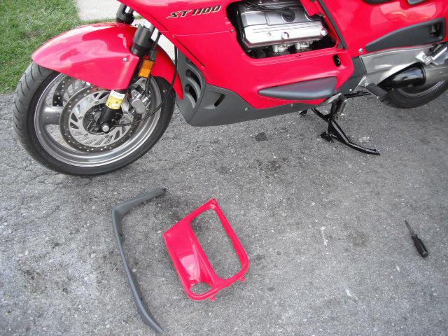
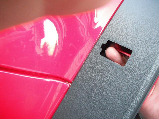
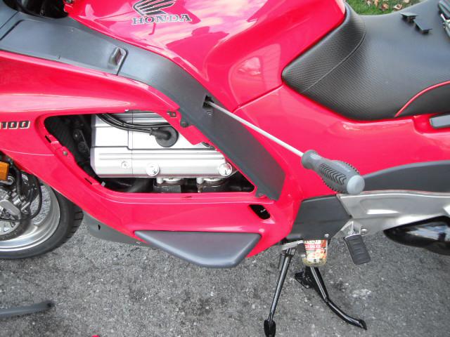
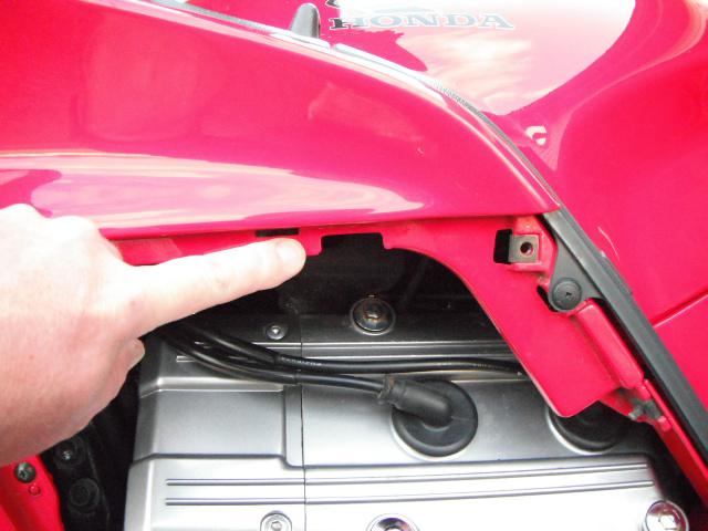
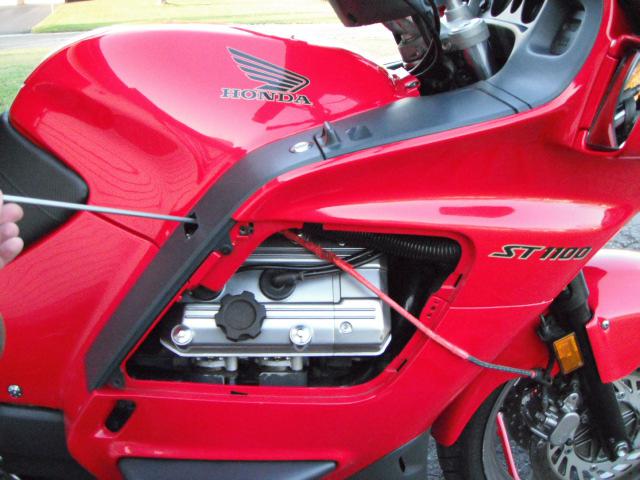
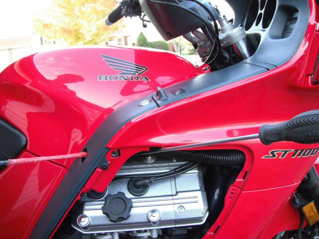
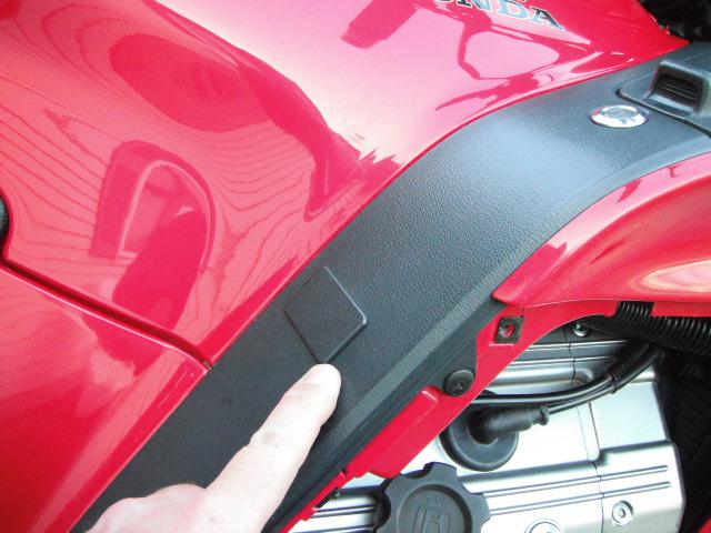
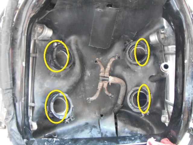
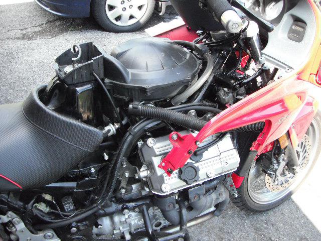
I first start by removing some of the body panels needed to gain access to the float bowl drain screws. I have to remove the (optional) fairing extensions / deflectors, center maintenance cover and the panel plugs.
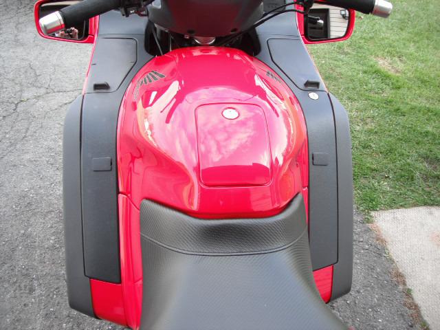
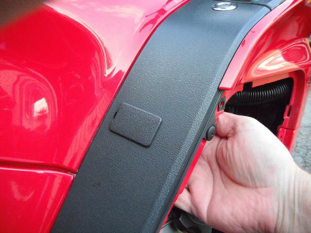
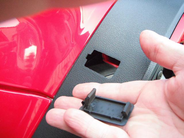
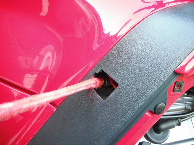
I always push out the panel plugs very carefully from the inside, out. Always a risk of damaging these cheesy plastic plugs by prying them out with a screw driver.
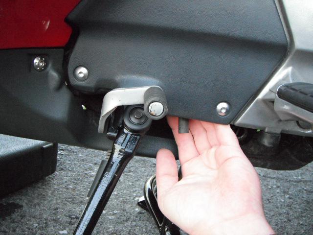
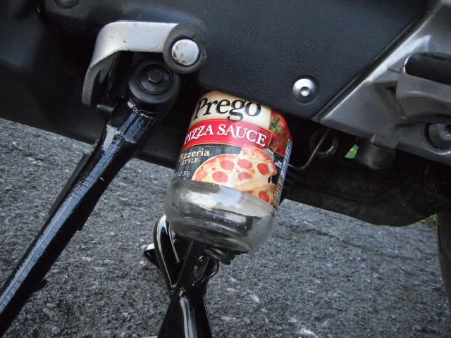
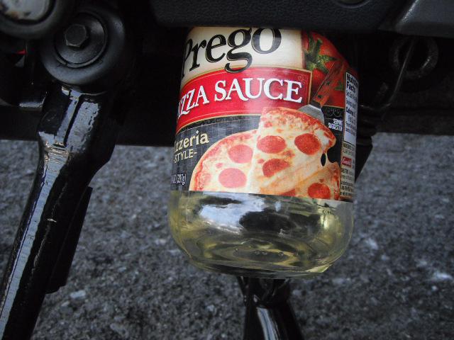
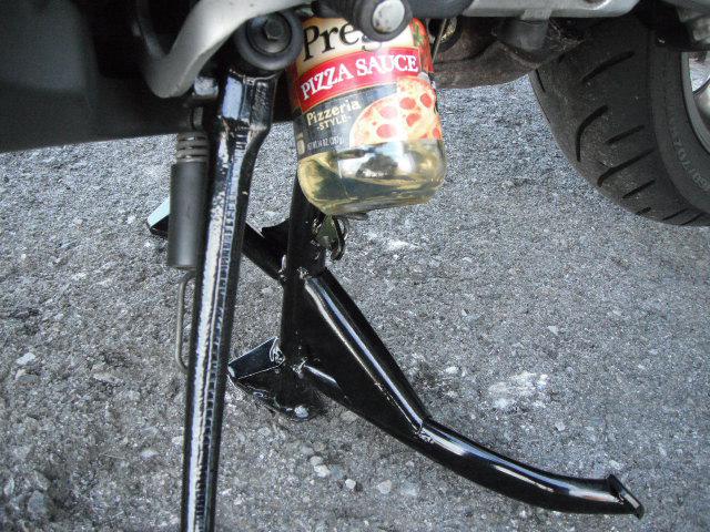
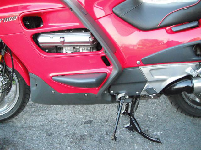
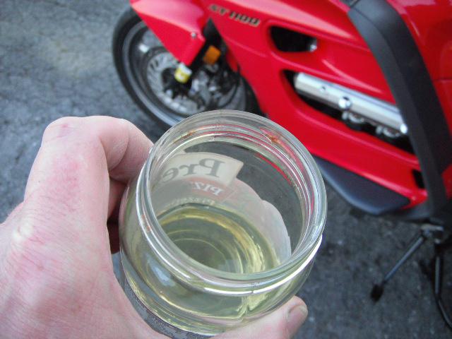
Now that everything is out of the way, I go to the recycle bin and get out a clean container to drain the fuel into. The carburetor’s drain hose is down at the bottom of the bike just behind the side stand pivot and shifter. This particular jar I used was able to be wedged up in the body panels and stayed firmly put. Even full of gas.
I have a long flathead screwdriver to get down into the bowl screws. This particular driver had to be ground down on the sides to reach into the recessed bowl body to get at the screw head. It’s a cheapo Harbor Freight driver that only gets used once a year for this job.
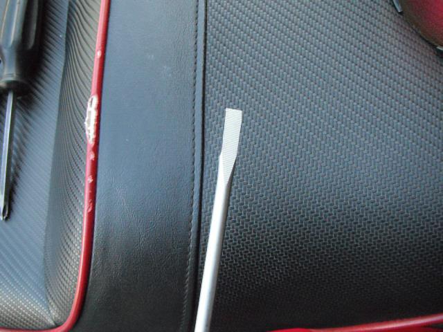
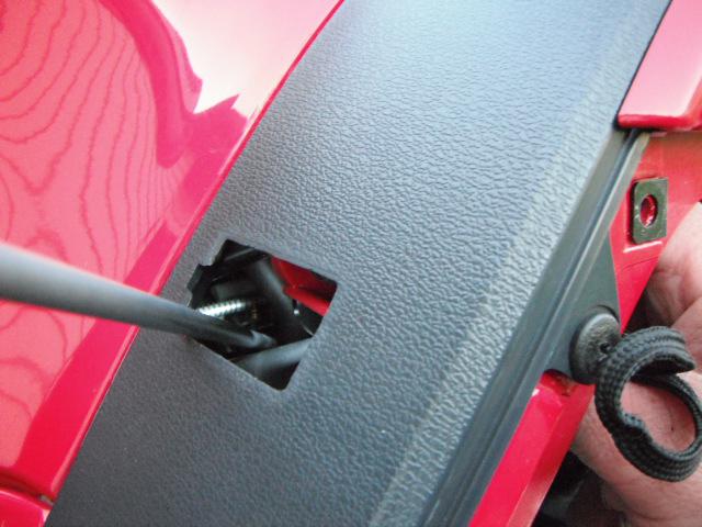
I suppose you could start were ever you want, but I do the easy side first. I always start off with doing #2 (left front) carb first, then work my way back and around to the other side. I tried to get the best pictures I could, but those screws are WAY down in there. Get the brightest flashlight you own to look in there!
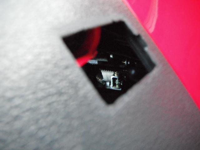
I hold the flashlight inside the bike while looking down through the plug hole. You’ll have to bend down the black rubber insulator mat with the driver, but the screw is easily viewed and accessed. I open it up a couple of turns and let it drain for a couple of minutes. I also leave the driver in the screw head while draining.
Now that #2 is drained, I tighten up the screw snug and move back to #4. Same procedure for #4, however you will need to use the cut-out in the fairing for driver clearance.
Getting more gas !
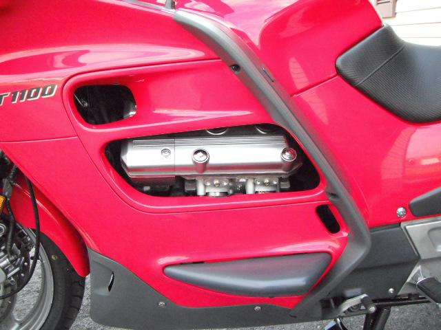
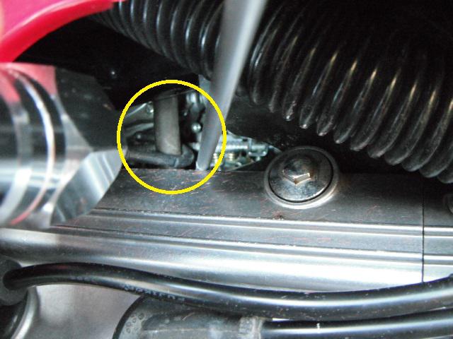
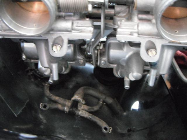
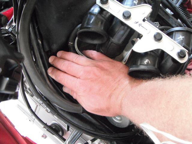
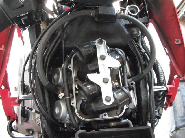
Now that #2 & #4 are drained, I move over to the right side of the bike and do #1 & #3. This side is tricky due to the engine breather hose that is routed right between the two carbs. Also, this side is a lot tighter for screwdriver clearance between the valve cover and the synchronization screws. Don’t disturb the synchro screws while getting the driver down in there!
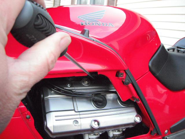
As I said before, it’s tricky getting around the breather hose. I use a bungee cord to pull the hose out of the way “gentlyâ€. If the hose was pulled on too hard, it may pull itself out of the air cleaner assy. I took the best pictures I could of how I do it.
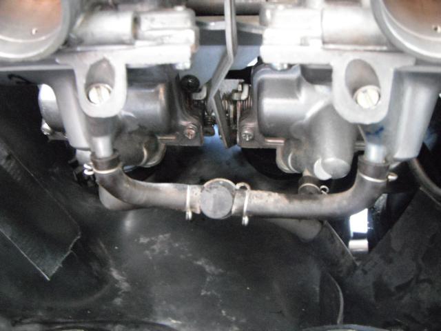
Here is a picture of the breather hose. Also notice how close the synchro screws are.
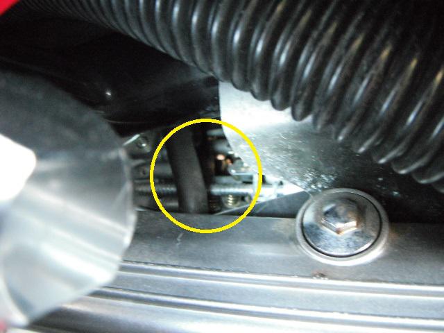
Unfortunately, the bungee has to be used for clearance on both right side carbs. Pull forward for #1 carb. Pull back for #3.
In this pic, you’ll notice the bungee hook around the breather hose as I drain #3 carb.
Now that the carbs are drained, I can re-assemble the body work. I always put the panel plugs back in first.
That’s it. I’m all done. Bike is back together and ready to be put away for the winter. It only takes me around a half hour to do the whole carb draining job from start to finish.
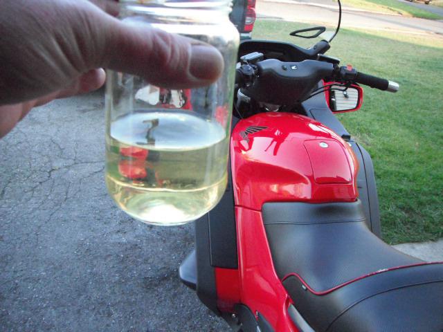
Here is the jar full of gas showing how much will come out. I peeled off the wrapper for better visibility. I’m also happy that there’s no junk in my carbs!
~~~
Thank You again for your contribution Adam Frymoyer, STOC #949
~~~
Carburetor Draining Procedure ( ST1100 )
For quite some time, I’ve been meaning to post a carb draining procedure for the ST1100. This year I finally took the time to take some pictures while I drain the carbs for winter storage. I strongly recommend carb draining for LONG TERM storage. My bike sits for 5 to 6 months, pending on winter conditions. It is also a good maintenance practice to drain out any contaminants (if any) of the float bowls into a clean container. If you see any crud while draining, there is a potential problem in the fuel system that needs to be looked into. Most guy’s don’t drain the carbs. They choose their favorite fuel stabilizer, add it to the tank, fill the tank, and walk away.... Most of them get away with it for a long time, but how many times a year do we help someone through a carb rebuild caused by sitting / storage? As always, this is just my opinion and the way I do it. Please follow the service manual for the proper way to work on your bike.
I first start by removing some of the body panels needed to gain access to the float bowl drain screws. I have to remove the (optional) fairing extensions / deflectors, center maintenance cover and the panel plugs.
I always push out the panel plugs very carefully from the inside, out. Always a risk of damaging these cheesy plastic plugs by prying them out with a screw driver.
Now that everything is out of the way, I go to the recycle bin and get out a clean container to drain the fuel into. The carburetor’s drain hose is down at the bottom of the bike just behind the side stand pivot and shifter. This particular jar I used was able to be wedged up in the body panels and stayed firmly put. Even full of gas.
I have a long flathead screwdriver to get down into the bowl screws. This particular driver had to be ground down on the sides to reach into the recessed bowl body to get at the screw head. It’s a cheapo Harbor Freight driver that only gets used once a year for this job.
I suppose you could start were ever you want, but I do the easy side first. I always start off with doing #2 (left front) carb first, then work my way back and around to the other side. I tried to get the best pictures I could, but those screws are WAY down in there. Get the brightest flashlight you own to look in there!
I hold the flashlight inside the bike while looking down through the plug hole. You’ll have to bend down the black rubber insulator mat with the driver, but the screw is easily viewed and accessed. I open it up a couple of turns and let it drain for a couple of minutes. I also leave the driver in the screw head while draining.
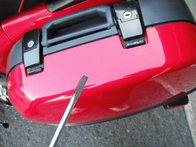
Now that #2 is drained, I tighten up the screw snug and move back to #4. Same procedure for #4, however you will need to use the cut-out in the fairing for driver clearance.
Getting more gas !
Now that #2 & #4 are drained, I move over to the right side of the bike and do #1 & #3. This side is tricky due to the engine breather hose that is routed right between the two carbs. Also, this side is a lot tighter for screwdriver clearance between the valve cover and the synchronization screws. Don’t disturb the synchro screws while getting the driver down in there!
As I said before, it’s tricky getting around the breather hose. I use a bungee cord to pull the hose out of the way “gentlyâ€. If the hose was pulled on too hard, it may pull itself out of the air cleaner assy. I took the best pictures I could of how I do it.
Here is a picture of the breather hose. Also notice how close the synchro screws are.
Unfortunately, the bungee has to be used for clearance on both right side carbs. Pull forward for #1 carb. Pull back for #3.
In this pic, you’ll notice the bungee hook around the breather hose as I drain #3 carb.
Now that the carbs are drained, I can re-assemble the body work. I always put the panel plugs back in first.
That’s it. I’m all done. Bike is back together and ready to be put away for the winter. It only takes me around a half hour to do the whole carb draining job from start to finish.
Here is the jar full of gas showing how much will come out. I peeled off the wrapper for better visibility. I’m also happy that there’s no junk in my carbs!
~~~
Thank You again for your contribution Adam Frymoyer, STOC #949
#29
ST1100 Archive of Wisdom / Re: Part numbers & Parts sourc...
Last post by KoTAOW - September 06, 2014, 05:28:22 PMSubmitted by Jon Ransom, STOC #063
~~~
The information below is the latest I could garner from searching the LiST.
I've checked each site today (9/5/2014) and each has fiche unless noted:
Bike Bandit
http://www.bikebandit.com/honda-motorcycle-parts/oem-parts
Chaparral Motorsports
http://www.chaparral-racing.com
Dennis Kirk
https://www.denniskirk.com
"no fiche;
ST listed with cruisers"
Discount Honda Parts
http://www.discounthondaparts.com
Honda Direct Line (aka HDLParts.com)
http://www.hondadirectline.com
Honda OnLine Parts
redirects to Honda Direct Line
Honda Parts Direct
http://www.hondaparts-direct.com
MR Cycles
http://www.mrcycles.com
Parts Fish
http://www.partsfish.com/
Parts Pit Stop
http://www.partspitstop.com/oemparts/c/honda/parts
Partzilla
http://www.partzilla.com/
Power Sports Plus
redirects to Partzilla
Powers Sports Pro
redirects to Parts Fish
Ron Ayers
http://www.ronayers.com
missing 1991
Service Honda
http://www.servicehonda.com
Zanotti Motors
http://www.zanottimotorcycles.com/
on-line closed 12/31/2011
~~~
These are more specialized.
None have fiche:
CBR Bearing Inc
http://www.servicehonda.com
THE BEARINGS SOURCE
David Silver Spares
https://www.davidsilverspares.com/home/
PJ Motorsports
http://pjmotorsports.com
Keihin & Mikuni carb parts
Sirius Consolidated Inc (S.C.I.)
http://www.siriusconinc.com
carb bits
~~~
Thank You again for your contribution Jon Ransom, STOC #063
~~~
Parts Sources Update ( ST1100/ST1300 )
The information below is the latest I could garner from searching the LiST.
I've checked each site today (9/5/2014) and each has fiche unless noted:
Bike Bandit
http://www.bikebandit.com/honda-motorcycle-parts/oem-parts
Chaparral Motorsports
http://www.chaparral-racing.com
Dennis Kirk
https://www.denniskirk.com
"no fiche;
ST listed with cruisers"
Discount Honda Parts
http://www.discounthondaparts.com
Honda Direct Line (aka HDLParts.com)
http://www.hondadirectline.com
Honda OnLine Parts
redirects to Honda Direct Line
Honda Parts Direct
http://www.hondaparts-direct.com
MR Cycles
http://www.mrcycles.com
Parts Fish
http://www.partsfish.com/
Parts Pit Stop
http://www.partspitstop.com/oemparts/c/honda/parts
Partzilla
http://www.partzilla.com/
Power Sports Plus
redirects to Partzilla
Powers Sports Pro
redirects to Parts Fish
Ron Ayers
http://www.ronayers.com
missing 1991
Service Honda
http://www.servicehonda.com
Zanotti Motors
http://www.zanottimotorcycles.com/
on-line closed 12/31/2011
~~~
These are more specialized.
None have fiche:
CBR Bearing Inc
http://www.servicehonda.com
THE BEARINGS SOURCE
David Silver Spares
https://www.davidsilverspares.com/home/
PJ Motorsports
http://pjmotorsports.com
Keihin & Mikuni carb parts
Sirius Consolidated Inc (S.C.I.)
http://www.siriusconinc.com
carb bits
~~~
Thank You again for your contribution Jon Ransom, STOC #063
#30
ST1100 Archive of Wisdom / Re: Carb Removal and Rebuild- ...
Last post by KoTAOW - August 12, 2014, 10:28:33 AMCarb Removal and Rebuild ( ST1100 )
PART FIVE:
Now that everything is assembled and checked over on the carb bank, I can now re-install the carbs back into the bike. It’s pretty much the same as before in doing the “reverse order†for the install. I’ve replaced the carb isolators / boots and have re-installed the black rubber heat shield.
When replacing the boots, don’t forget to install them with the raised tangs “facing out†as seen in the picture. This will aid in setting the carbs down into the boots. There are also notches at the bottom of the boots that have to be placed into the tab on the intake manifold. At this point, also rub a LIGHT film of grease, Vaseline, die electric paste, etc, around the insides of the boots, and on the outsides of the carb flange’s to also aid in installation. This must be done!
I then hold up the carbs down in the valley and hook up the float drain hoses. They push on easily. Make sure that the cut-outs in the rubber heat shield stay in their correct position.
I then let the carb bank sit inside the valley (back side tilted up) and hook up the throttle cables.
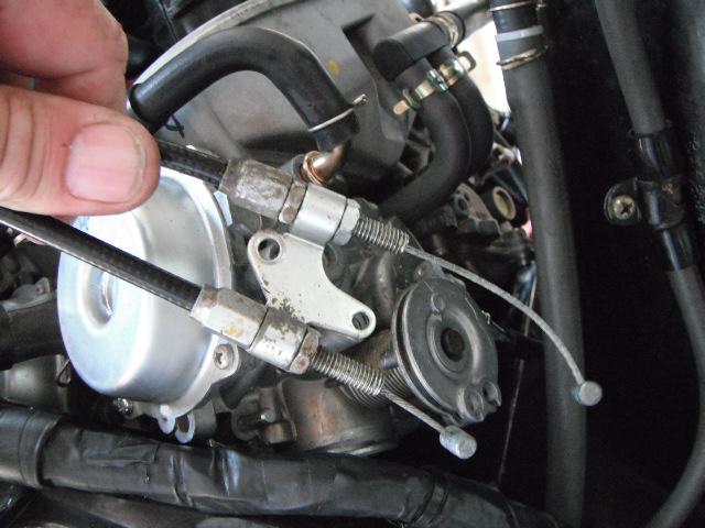
Getting the carbs into the boots is super easy. There is no need for crow-bars, broom handles, greased plexi-glass, bungee cords, ratchet straps, rubber mallets, etc. Here is the trick: Earlier, I’ve already lightly coated the insides of the boots and the outsides of the carb flanges with grease. I set the RIGHT side of the carb flanges fully down into the boots as you can see in the picture.
The LEFT side as you can see, is just sitting inside of the raised boot flanges.
I then take my right hand and put it centered on the carb intake plenum. With a GOOD FIRM push down, they will “snap†right in place, into the boots. Works every time.
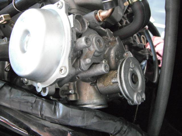
I will then tighten up all of the carb clamps, install choke cable and other top end components. I am also eliminating the auto vacuum fuel shut down valve. These are well known to fail at any given time. Leaking vacuum, or leaking fuel. I went 85,000 on my other ST without the valve, so this one gets the same treatment.
See that BRAND NEW HONDA OEM FUEL FILTER? I strongly recommend that one be used. I’ve seen lot’s of carb float bowls and jets with silt, sand, debris, rust, etc, by using universal aftermarket “screen†type filters. Not to mention debris stuck between the float needles and seats. I've just spent several day’s cleaning and setting up the carbs properly. No need to ruin the job by using a universal fly-by-night, junk fuel filter / screen. Just sayin’.....
The OEM Honda filter is $12 at my dealer and gets replaced every other year. Take pride in your work and don’t let ANYTHING get into those fresh carbs! Also consider a new air filter. Preferably the Honda OEM. The carbs are jetted to work with this air filter. Anything else may change the mixture and / or allow more grit into the intake.
Next, I always double check that everything is tight and installed. Check the linkage and cable operation for throttle and choke.
Now that everything is hooked up, I can start it up and check for leaks, etc. It runs like crap when first started. It always will. I just disturbed all of the carb linkages and synchro screws, springs, etc., when everything was apart. I shut it down and look things over. Good to go. I then hook up my carb sticks and synchronize the carb’s first. They will always be WAY out. But after adjustment, it’s now Smoooooth.... I also performed the idle drop and then re-synchronize the carb’s. So.... Sync, idle drop, re-sync is the procedure. Also remember that you’ll need to get a BIG fan or blower in front of the radiator to prevent the engine cooling fan from coming on. When the cooling fan comes on, it puts an electrical load on the alternator, which in turn lowers the idle speed. When the idle speed drops, all of the readings on the carb balancer will change quite a bit. You’ll be there for a long time trying to get the carbs balanced fighting engine cooling fan load. It’s that sensitive. Same goes for the idle drop. I set idle speed to 1000 rpm with the bigger pilots.
After that, it’s time to finish installing the rest of the top side. Air filter housing, filter, lid, etc.
I then put on the seat and take it out for a good run, up to operating temp. Everything is working fantastic, and the V-4 is running the way it was intended with those new pilot’s and the fresh tune. I can now finish assembly and put all that plastic back on. DONE !!!