- Welcome to ST-Riders - The liST.

The Original ST1100/ST1300 Forum
Recent posts
#31
ST1100 Archive of Wisdom / PAIR Removal ( ST1100 ) *
Last post by KoTAOW - August 12, 2014, 10:20:54 AMSubmitted by Adam Frymoyer, STOC #949
~~~
Over the years, there have been several very high mileage bikes in the ST1100 community that have had their PAIR valve diaphragms fail, causing a vacuum leak and drivability issues. When I say several have failed, I mean several. I know of only 3 guys that have had an actual failure of the PAIR valves themselves. A vast majority of the others have been from vacuum hoses getting dry rotted, cracking, disintegrating and causing loads of trouble. Some guys like them and leave them alone. Others don’t want a problem in the future and remove them as a preventative measure. A very few, have to leave them on and service them to meet local emission inspection regulations. I already had the carburetors out for overhaul and I don’t want to take them out again to fix a non-meaningful emission component. I also had coolant leaks at the elbows and the coolant hoses were mush. Another bonus to PAIR removal is a little lost weight and less complexity. With that said, mine are coming out.... And with good reason! You’ll see as you read on, that it was a great preventive step. I would have had problems in the future....
There are many articles in the ST Archive Of Wisdom (AOW) for body work removal, carb removal and different ways to block off the PAIR pipes. Have a look at them for guidance. There are many great idea’s. However, refer to your Honda service manual to properly work on your bike. Some of the pictures I posted are just for reference, to give you a general idea of where I’m at.
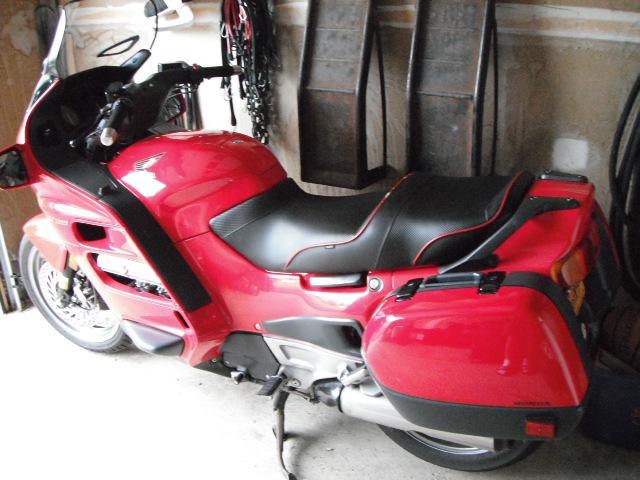
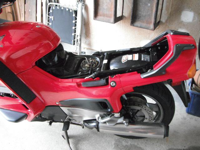
The first thing I do is take off most of the body work. I’ll need to also remove the fairing lowers and fairing centers to gain access to the chrome pipes.
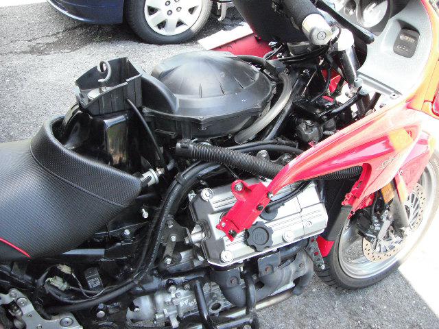
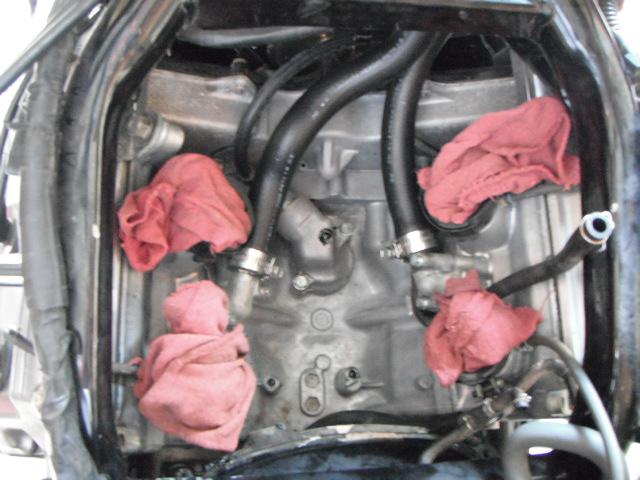
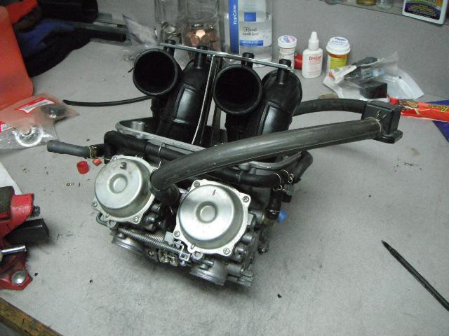
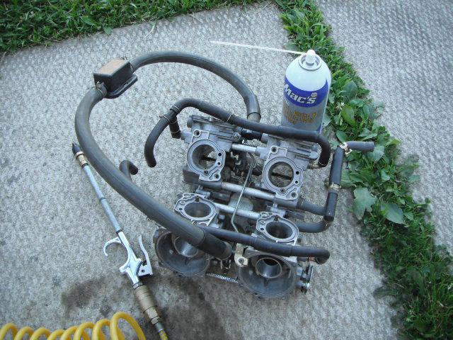
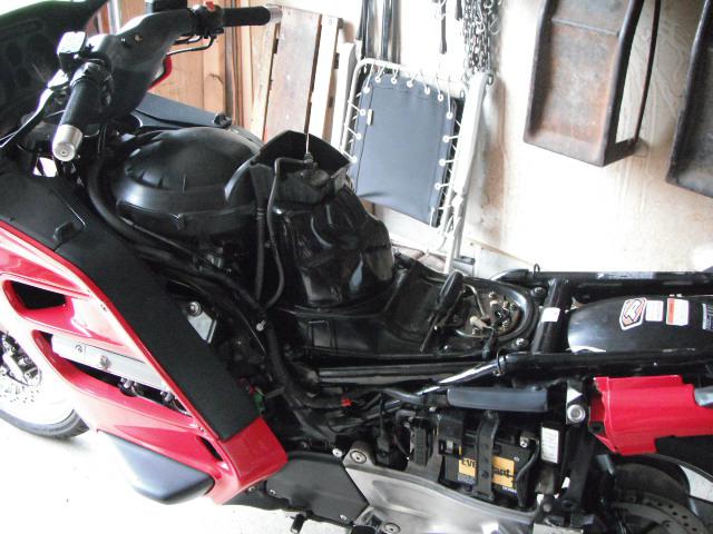
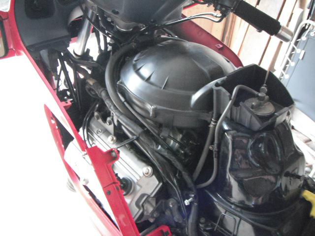
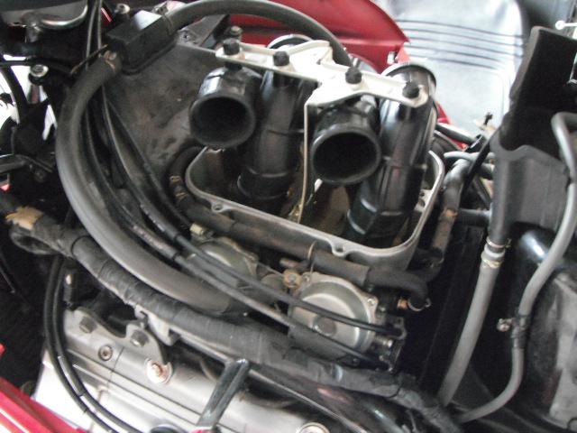
The next thing I do, is to remove the carburetor’s and rubber heat shield. YUK... Full of mouse pooh and pee.
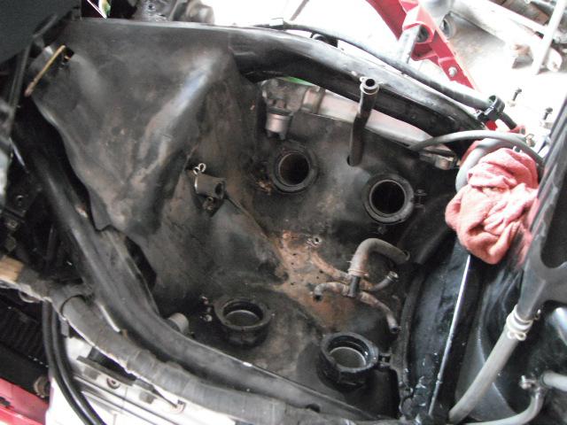
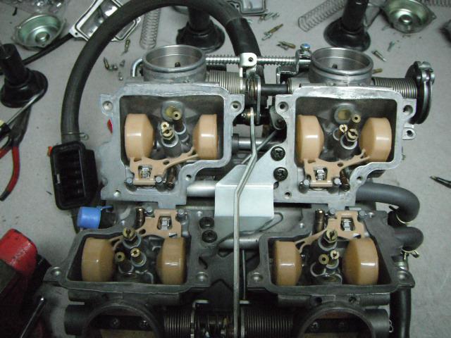
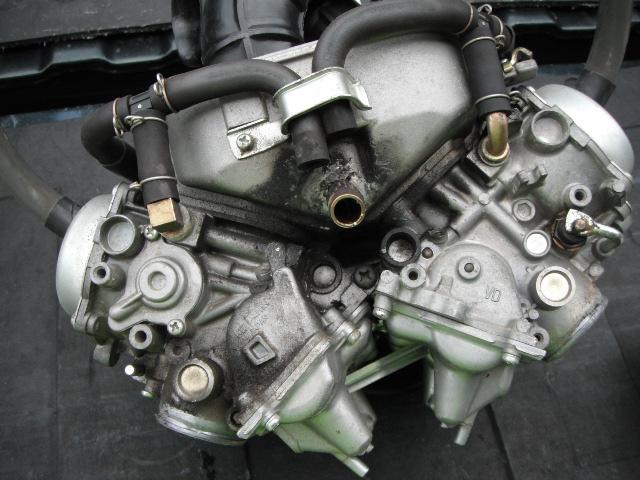
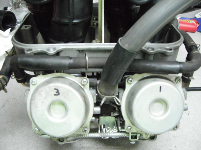
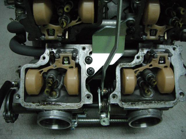
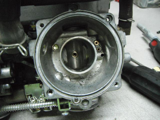
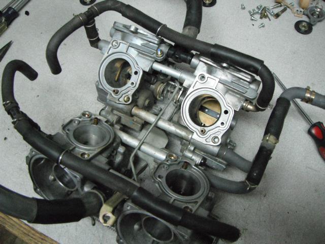
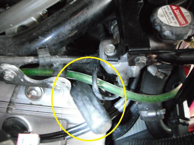
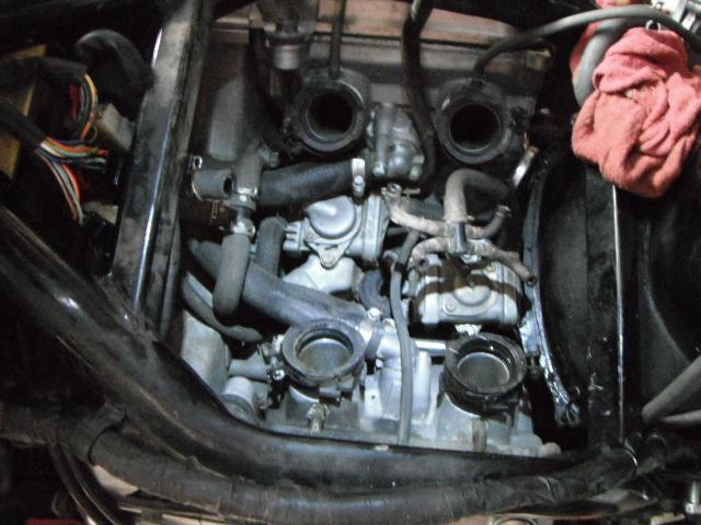
The PAIR system is now exposed.
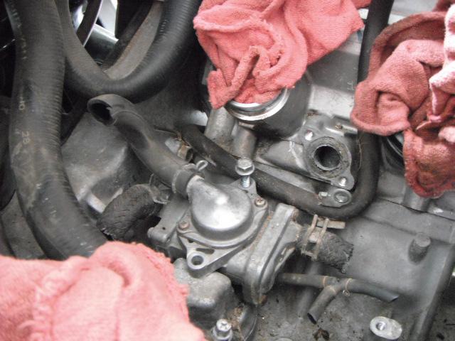
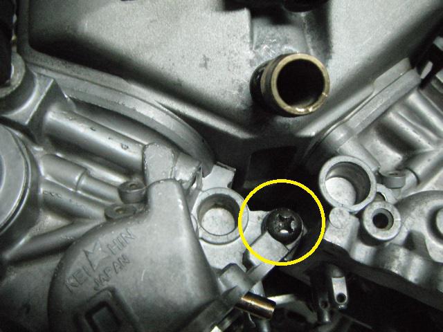
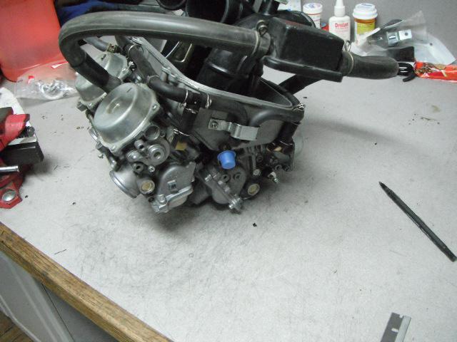
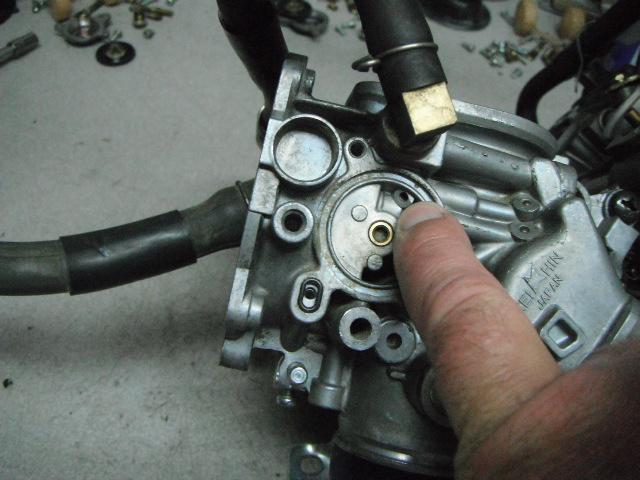
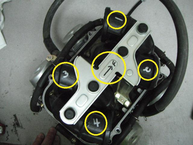
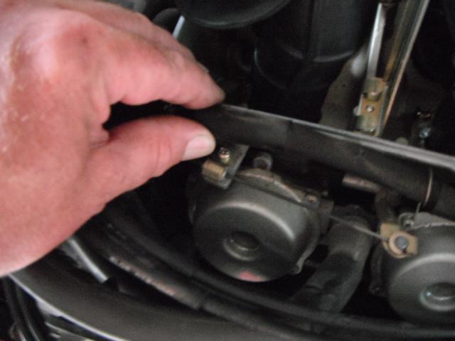
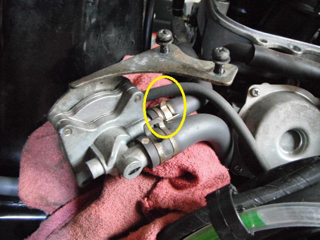
The front mounted valve CANNOT be removed without cooling system being drained and the right coolant elbow removed. There is not enough clearance to get the right mounting bolt loose and out.
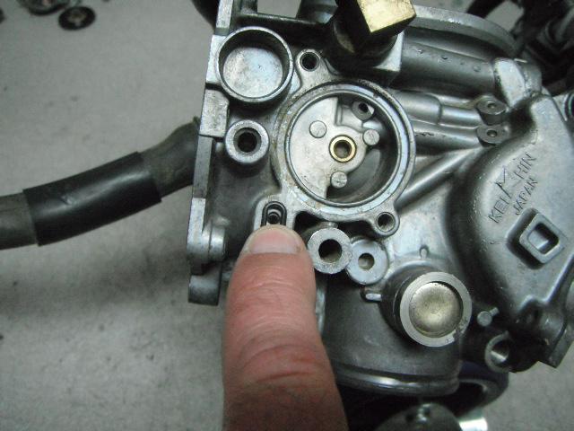
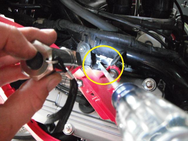
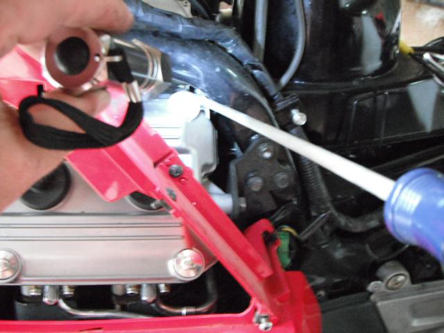
As you can see here, even with the right coolant hose removed, there still isn't enough clearance.
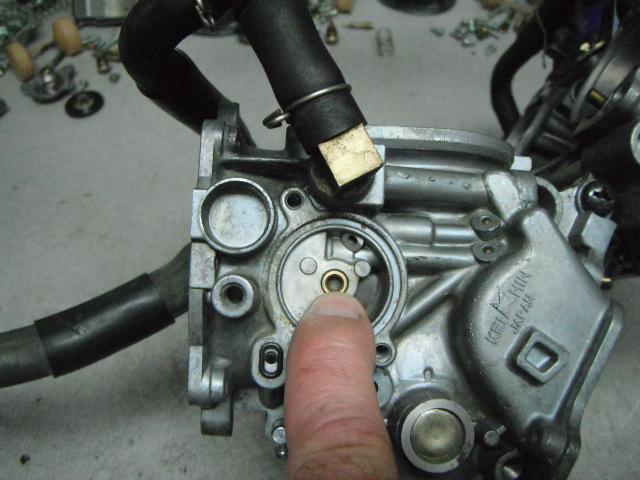
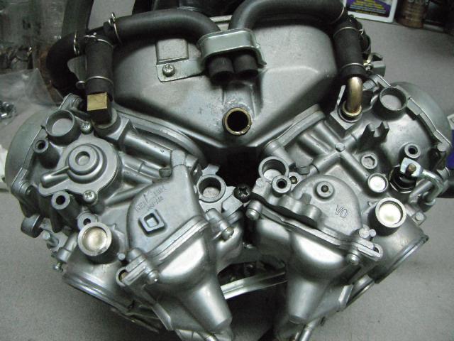
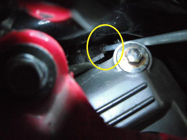
Now that the elbow is removed, the mounting bolt can now be taken out.
There’s no way that these elbow o-rings will re-seal. They MUST be replaced.
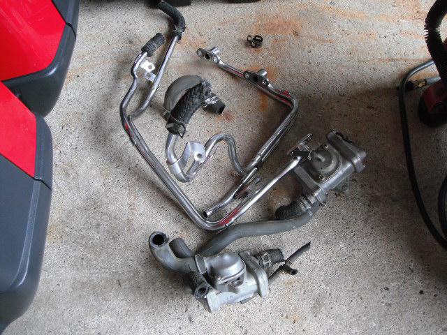
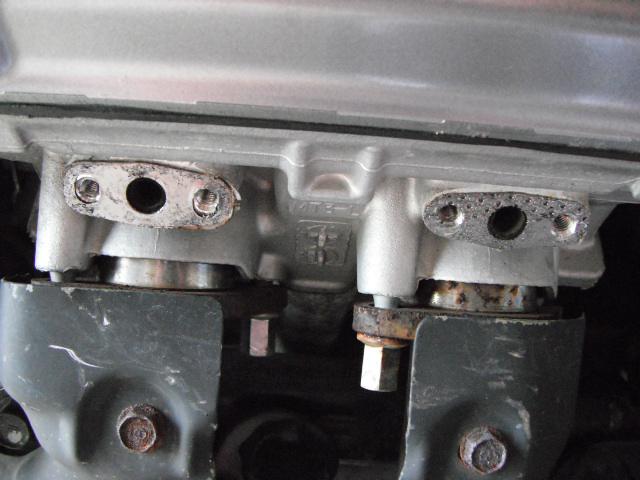
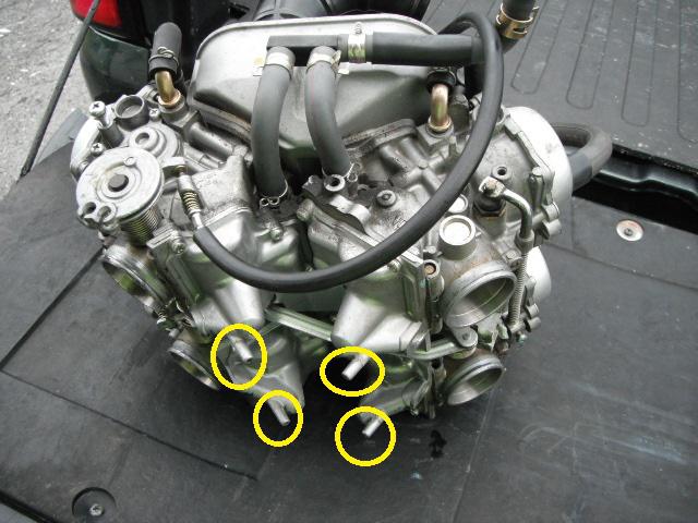
I then cut all of the hoses out with a pair of cutting pliers, un-bolt the valves and pull everything out. I then un-bolt the chrome tubes from the cylinder heads. The chrome pipes need to get bent, to work them around the cylinder heads and frame for removal.
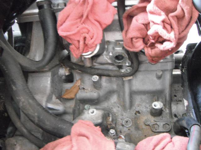
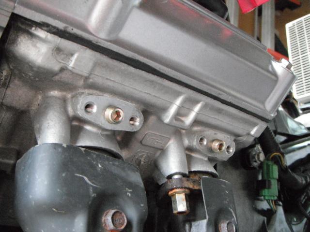
Here is what it looks like with everything removed. I also take dabs of silicone and fill the thread holes. I don’t want water to sit down in there and possibly freeze during winter storage.
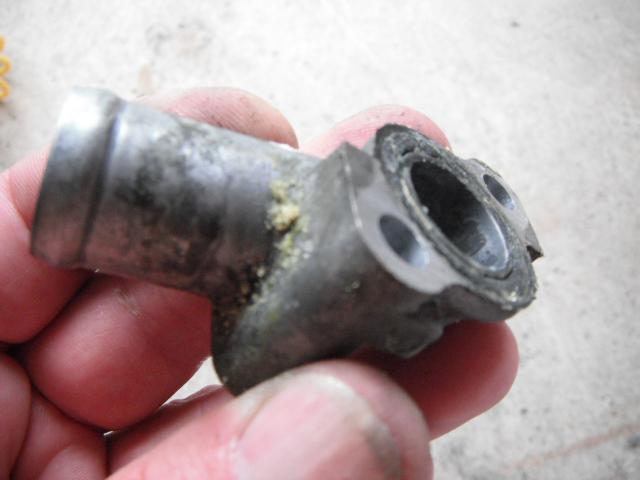
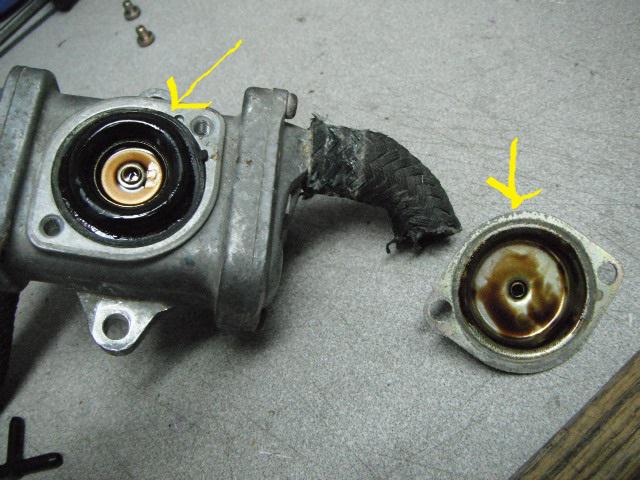
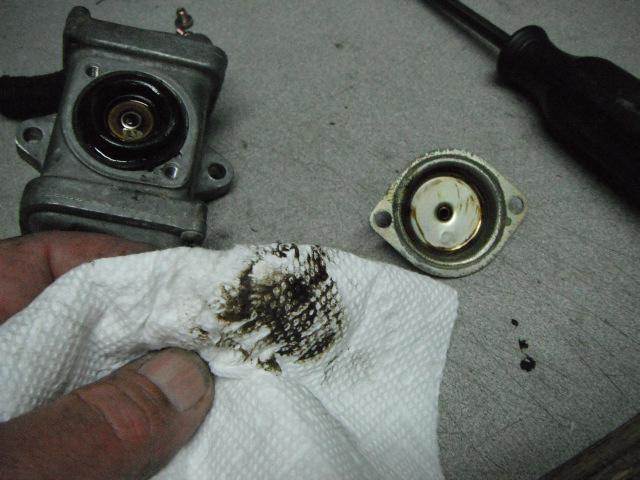
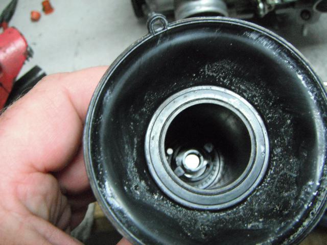
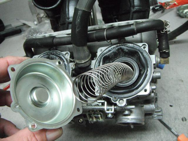
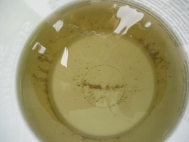
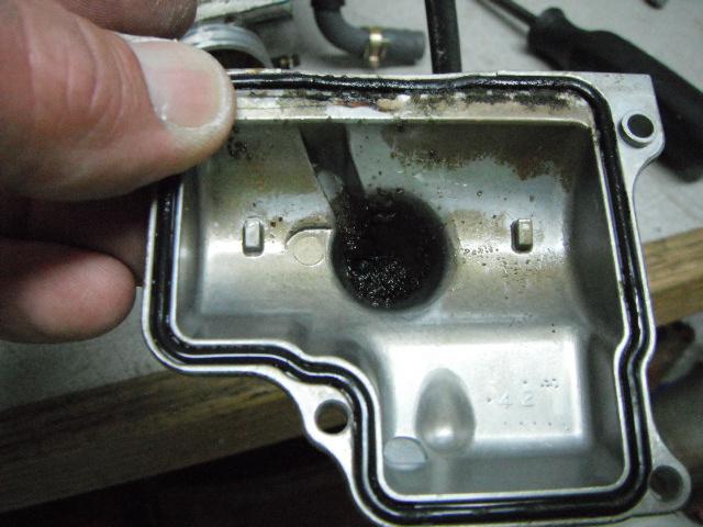
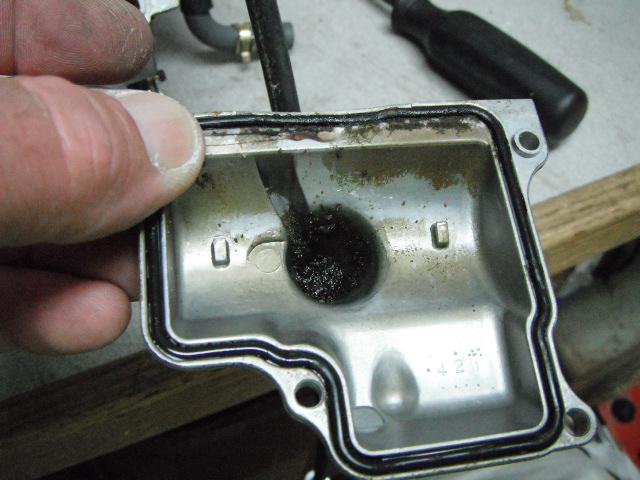
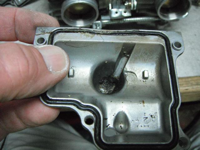
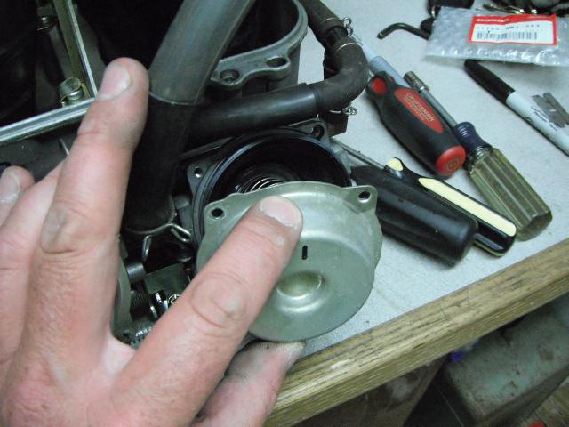
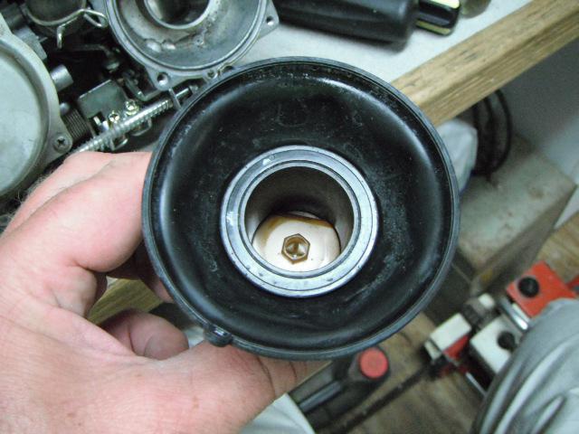
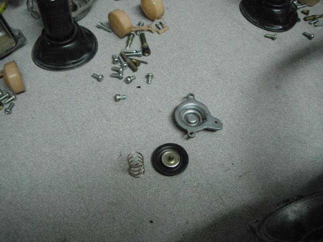
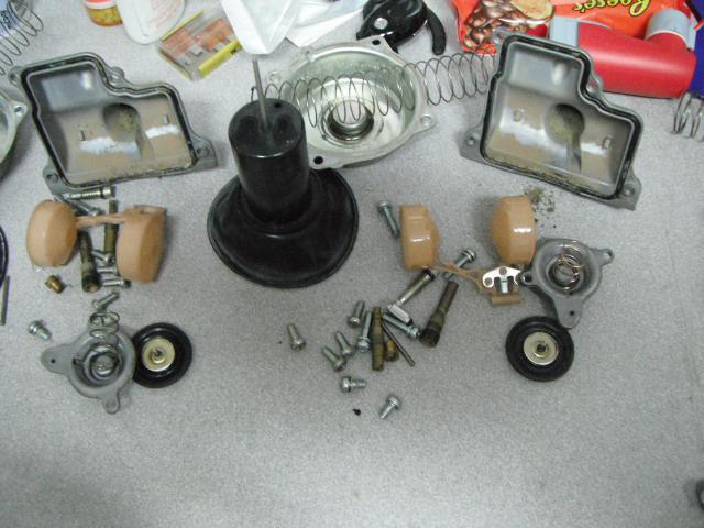
With everything removed, I noticed a brown fluid leaking onto the garage floor. What the heck... It’s coming out of the PAIR valves. I took them into the shop and took them apart before I throw them away.
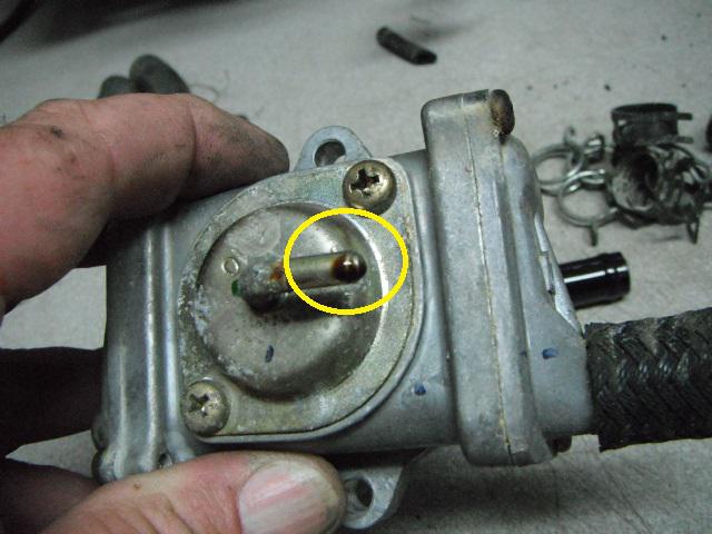
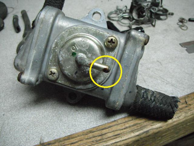
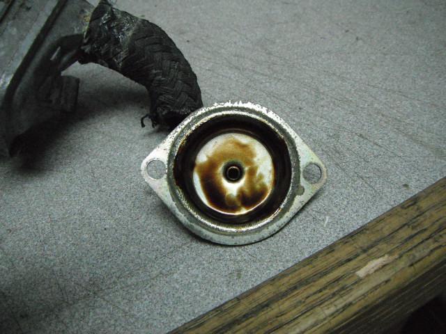
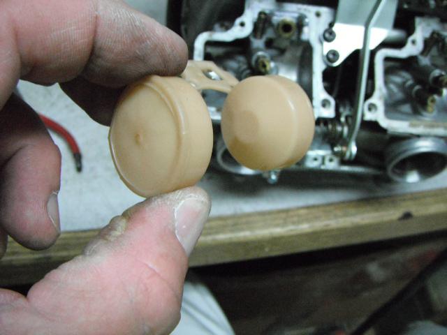
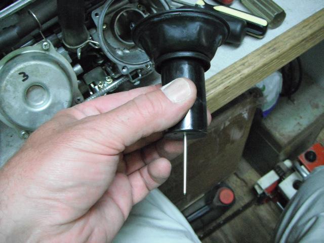
With the covers removed, I find brown stinky slime in the housings. The rubber diaphragms are mush and starting to distort. I’m glad I took them out. As said earlier, I would have had problems in the future.
Now that the PAIR valves are out, I de-greased the valley of the engine. I also replaced all of the coolant elbow o-rings, water manifold o-ring and seal and coolant hoses going from the block to the thermostat housing. This is also a better look at the silicone down in the thread holes.
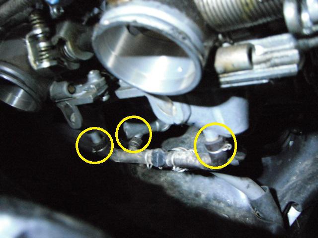
I can now remove all of the vacuum “T’s†and cap off both sides. I've also eliminated the auto vacuum fuel-cut valve.
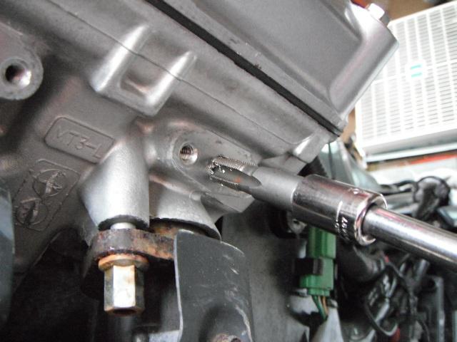
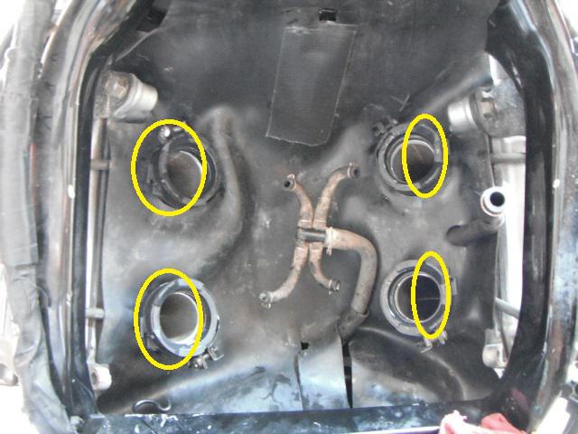
I then scrape off all of the gasket material from the cylinder heads. As I said earlier, there are many different ways to block these ports off. I don’t want the pipes in there. Just my personal preference. I took a 1/8†NPT tap and thread the ports. I then take the extra plugs out of an air brake governor kit I've got kicking around and install them in the heads. Use your imagination and be creative to whatever you find the most attractive. I’m just a function over form guy...
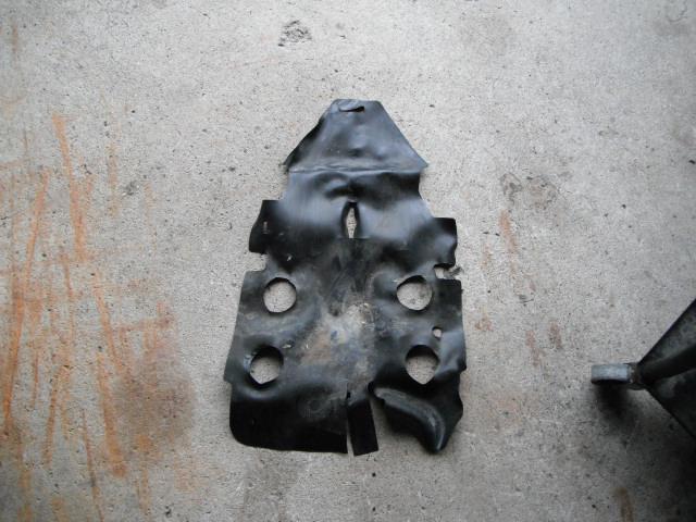
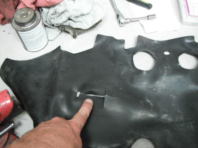
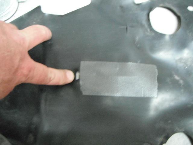
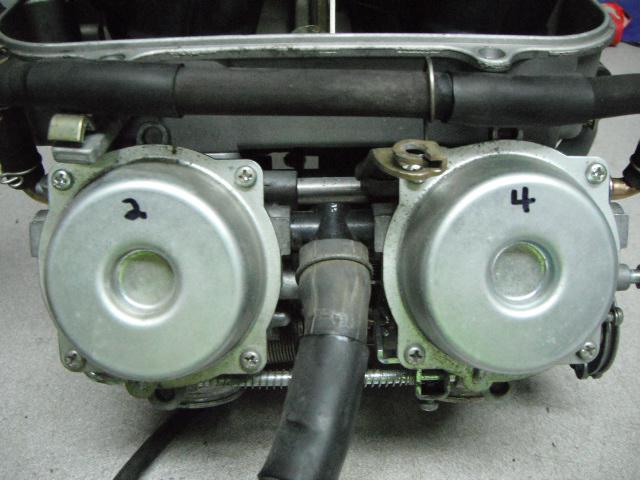
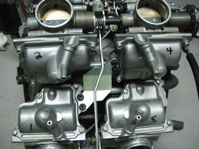
During the carburetor overhaul, I’ve already replaced the rubber isolator / boots and ready to install the rubber heat shield. I first tape up the cut-outs in the shield with heat tape on both sides. These slots won’t be used anymore now that the PAIR valves are out. I don’t want any extra heat getting up to the carb float bowls. It gets really hot down in there! However, I still leave the little slot open to hook to the frame for mounting support.
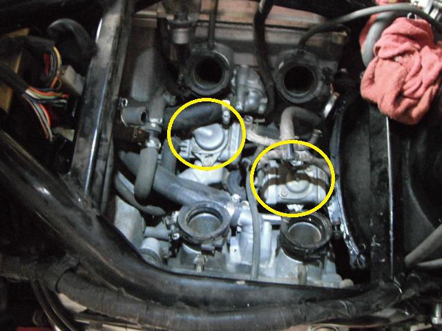
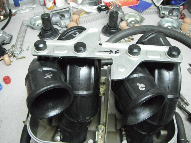
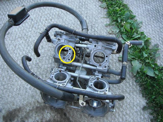
Now that this is done, I can put the shield in. I strongly recommend replacing those carb boots. They get dry, brittle and leak as they age. If replacing, remember to face the raised tabs outwards as shown / circled.
That’s it for a PAIR removal. I can now re-install the carbs, accessories and body work.
~~~
Thank You again for your contribution Adam Frymoyer, STOC #949
~~~
PAIR Removal
Over the years, there have been several very high mileage bikes in the ST1100 community that have had their PAIR valve diaphragms fail, causing a vacuum leak and drivability issues. When I say several have failed, I mean several. I know of only 3 guys that have had an actual failure of the PAIR valves themselves. A vast majority of the others have been from vacuum hoses getting dry rotted, cracking, disintegrating and causing loads of trouble. Some guys like them and leave them alone. Others don’t want a problem in the future and remove them as a preventative measure. A very few, have to leave them on and service them to meet local emission inspection regulations. I already had the carburetors out for overhaul and I don’t want to take them out again to fix a non-meaningful emission component. I also had coolant leaks at the elbows and the coolant hoses were mush. Another bonus to PAIR removal is a little lost weight and less complexity. With that said, mine are coming out.... And with good reason! You’ll see as you read on, that it was a great preventive step. I would have had problems in the future....
There are many articles in the ST Archive Of Wisdom (AOW) for body work removal, carb removal and different ways to block off the PAIR pipes. Have a look at them for guidance. There are many great idea’s. However, refer to your Honda service manual to properly work on your bike. Some of the pictures I posted are just for reference, to give you a general idea of where I’m at.
The first thing I do is take off most of the body work. I’ll need to also remove the fairing lowers and fairing centers to gain access to the chrome pipes.
The next thing I do, is to remove the carburetor’s and rubber heat shield. YUK... Full of mouse pooh and pee.
The PAIR system is now exposed.
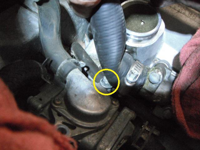
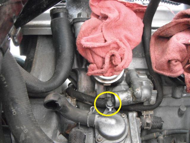
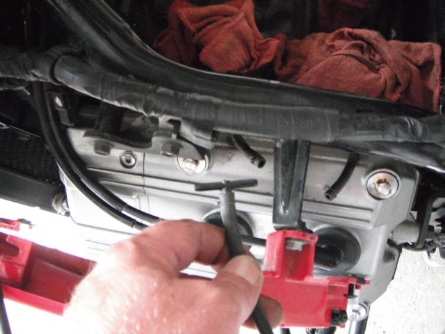
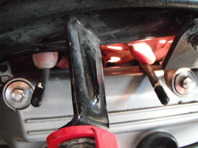
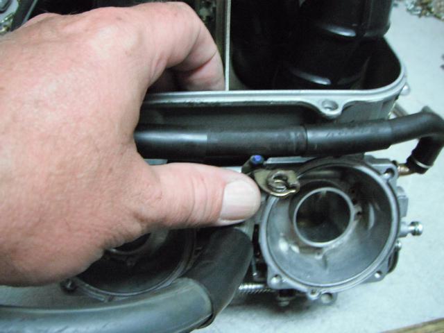
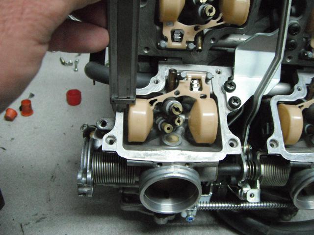
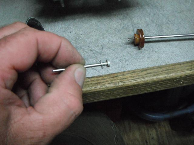
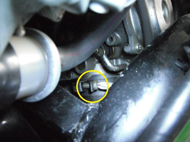
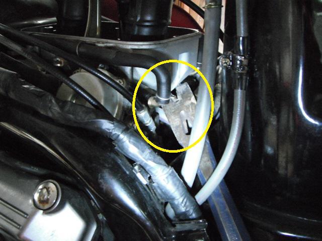
The front mounted valve CANNOT be removed without cooling system being drained and the right coolant elbow removed. There is not enough clearance to get the right mounting bolt loose and out.
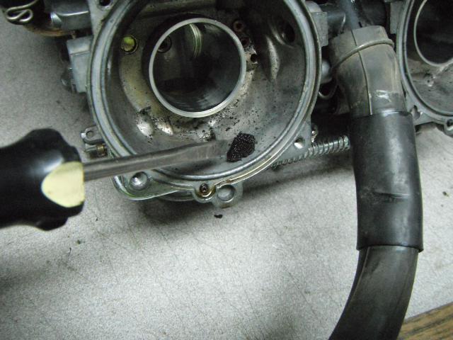
As you can see here, even with the right coolant hose removed, there still isn't enough clearance.
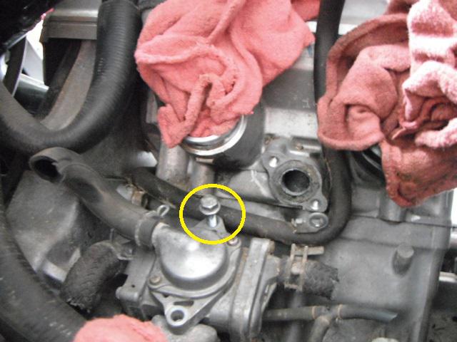
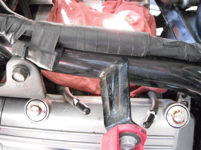
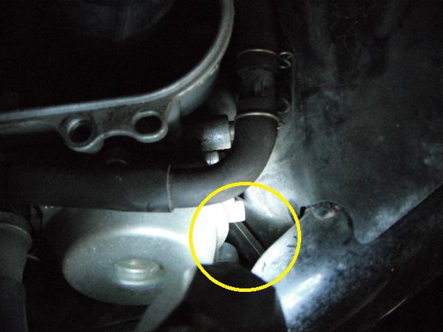
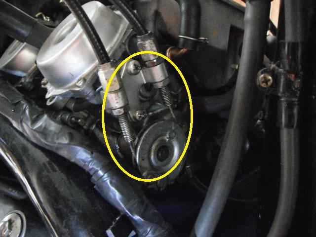
Now that the elbow is removed, the mounting bolt can now be taken out.
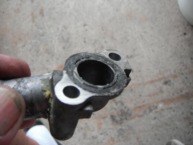
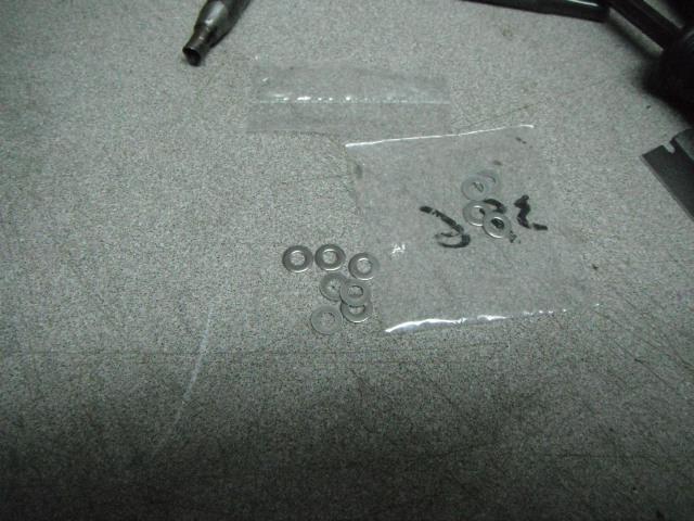
There’s no way that these elbow o-rings will re-seal. They MUST be replaced.
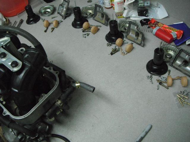
I then cut all of the hoses out with a pair of cutting pliers, un-bolt the valves and pull everything out. I then un-bolt the chrome tubes from the cylinder heads. The chrome pipes need to get bent, to work them around the cylinder heads and frame for removal.
Here is what it looks like with everything removed. I also take dabs of silicone and fill the thread holes. I don’t want water to sit down in there and possibly freeze during winter storage.
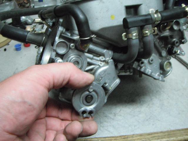
With everything removed, I noticed a brown fluid leaking onto the garage floor. What the heck... It’s coming out of the PAIR valves. I took them into the shop and took them apart before I throw them away.
With the covers removed, I find brown stinky slime in the housings. The rubber diaphragms are mush and starting to distort. I’m glad I took them out. As said earlier, I would have had problems in the future.
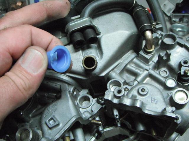
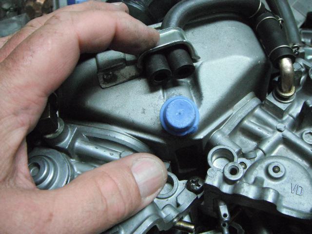
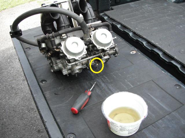
Now that the PAIR valves are out, I de-greased the valley of the engine. I also replaced all of the coolant elbow o-rings, water manifold o-ring and seal and coolant hoses going from the block to the thermostat housing. This is also a better look at the silicone down in the thread holes.
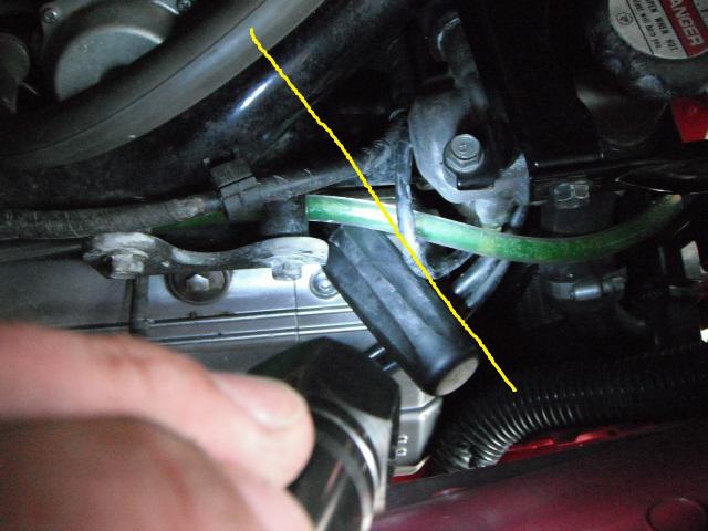
I can now remove all of the vacuum “T’s†and cap off both sides. I've also eliminated the auto vacuum fuel-cut valve.
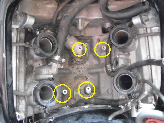
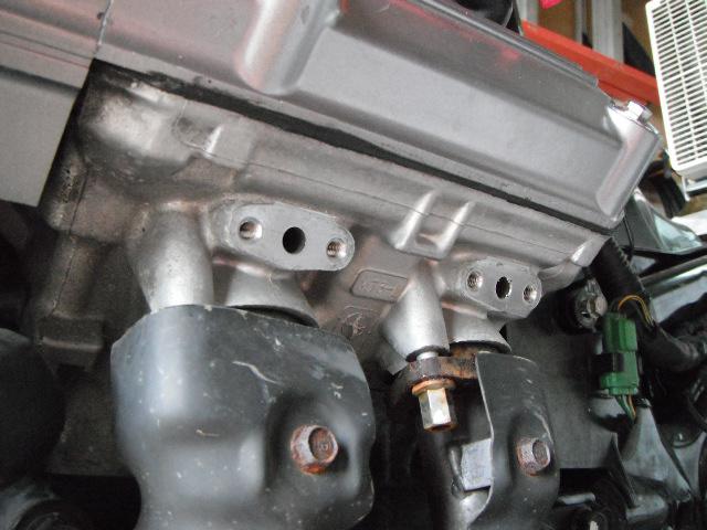
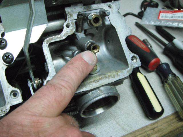
I then scrape off all of the gasket material from the cylinder heads. As I said earlier, there are many different ways to block these ports off. I don’t want the pipes in there. Just my personal preference. I took a 1/8†NPT tap and thread the ports. I then take the extra plugs out of an air brake governor kit I've got kicking around and install them in the heads. Use your imagination and be creative to whatever you find the most attractive. I’m just a function over form guy...
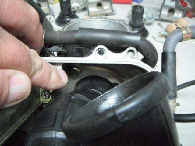
During the carburetor overhaul, I’ve already replaced the rubber isolator / boots and ready to install the rubber heat shield. I first tape up the cut-outs in the shield with heat tape on both sides. These slots won’t be used anymore now that the PAIR valves are out. I don’t want any extra heat getting up to the carb float bowls. It gets really hot down in there! However, I still leave the little slot open to hook to the frame for mounting support.
Now that this is done, I can put the shield in. I strongly recommend replacing those carb boots. They get dry, brittle and leak as they age. If replacing, remember to face the raised tabs outwards as shown / circled.
That’s it for a PAIR removal. I can now re-install the carbs, accessories and body work.
~~~
Thank You again for your contribution Adam Frymoyer, STOC #949
#32
ST1100 Archive of Wisdom / Re: Carb Removal and Rebuild -...
Last post by KoTAOW - August 11, 2014, 08:13:54 PMCarb Removal and Rebuild ( ST1100 )
PART FOUR:
Assembling the carbs is pretty straight forward. Pretty much just “reverse order†of taking them apart. The first thing I do, is put the plenum / tube assembly back on the top. This gives me the rigidity needed for final assembly. I loosen the pivot screws just a little and the 4 bottom bracket screws that join’s everything together. This will give me a little “wiggle room†for alignment.
Setting the plenum down on top and getting the dowels to align can be a challenge. I always get one side of the dowels “just†started on one side, then PATIENTLY wiggle the other side down in. Bending and flexing the carb bank back and forth until all the dowels are in. It will take multiple times to get it set! Do not use the big plenum screws to draw it down, or a hammer. This will only bend, ruin and destroy the threads and dowels. Once the dowels are started on all 4 carbs, carefully put in the big plenum screws and only start them several threads. Check and make sure all of the rubber intake tubes are aligned properly with their prospective vent holes and vent tubes! Do this before tightening down the plenum. Once everything is aligned, the plenum will push right down into place. Then lightly snug the big plenum screws. I then tighten the pivot screws and bottom bracket. Then go back and final torque the big plenum screws and bend the tabs back over the screw heads.
I then MAKE SURE that the choke and throttle linkages operate smoothly and everything is aligned and secured.
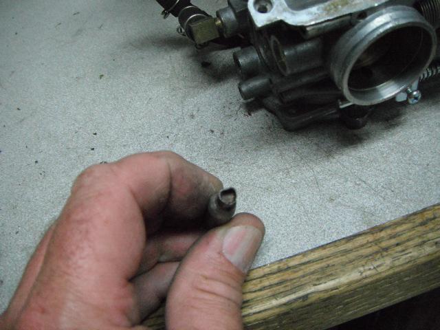
Because I removed the PAIR system, I glued on a plastic cap to the breather nipple.
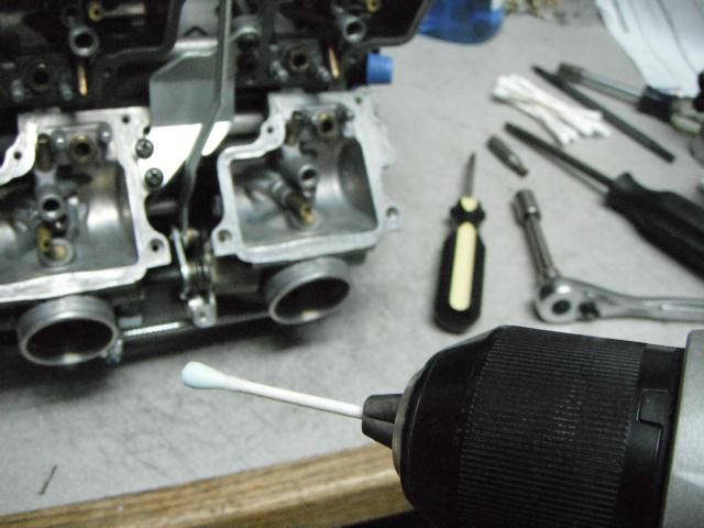
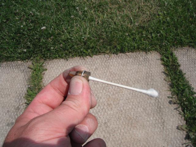
Flipping the carbs back over, I install the float seats. Because I’m re-using the needles and seats, I’m going to make sure I have no problems after assembly. I use Q-tips in a cordless drill with a little dab of metal polish on the Q-tip. This polishes the seating surface for the needle, making it like new. Remember that I cleaned the needle tips earlier.
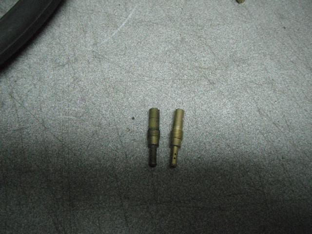
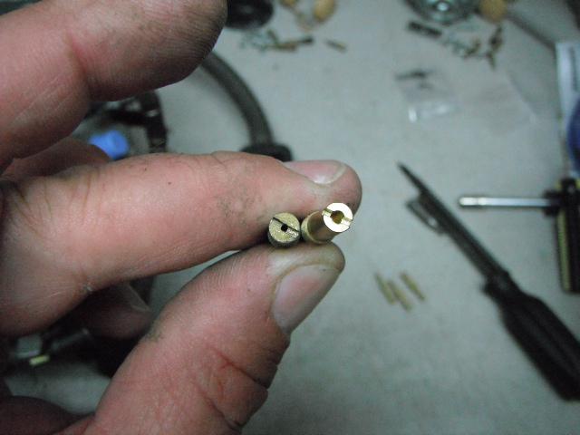
Next, I will be installing all of the jets, etc. It’s pretty straight forward. Just remember NOT to over torque anything. Brass jets going into aluminum threads.... I start off with the pilots. I’m showing some differences between the Honda OEM #38 pilots, verses the #40 Keihin jets. Big difference.
REASONS to change the PILOT and MAIN jets:
To meet strict emission laws, the factory really has to run the mixtures lean. This is done at idle and at low rpm. The bike is on its kickstand or centerstand. An exhaust analyzer goes up the tail pipe for testing at low rpm. To meet these regulations, the factory sets up the carbs to pass Federal EPA standards.
Some states such as California, have even stricter regulations. For Honda or any other manufacture, the idle mixture and pilot circuits at set very lean to meet these regulations. Example all ST1100 49 State bikes have #38 sized pilots and #128 main jets, while the California and ABS bikes have a #38 pilot and #125 main jets. All US bikes got PAIR valves. If you look in the service manual, you'll see that non-emission countries (at that time) receive #40 pilot jets and #128 mains with a different idle mixture screw count AND no PAIR valves. After some experimenting and goofing around with different jets and settings, I've found that the pre-emission Canadian specs are the OVERALL best tune for the ST1100. Overall meaning, the best fuel economy, with the best power output and smoothest running. It's always a compromise with carburetion, that's why technology has brought us fuel injection(fuel injection not absolutely perfect either). This is the reasoning behind me changing the pilots to a bigger size and tuning the idle mixture screws to match their fuel rate.
The ST1100 responds VERY well to the upgrade, pulling much harder down low (off idle) and fantastic mid-range power. The main jets do not get changed because it carburets perfectly with the #128. California and ABS bikes respond very well to all of the changes, including changing the mains from #125 to #128.
Emulsion tubes, main jet’s, etc, get put back in. The Idle mixture screw settings have been somewhat of a controversial topic in the ST community over the years. If in doubt, refer to your manual. Some guys count the screw turn’s from lightly seated during dis-assembly, then put them back in the original factory settings when putting them back in. Some guys take the average of the screw turns and set them ALL at that average. The most common being around 2 - 2 1/2 turns out. Another thing is that hardly anyone has the special tool to do the idle drop procedure. None of them are wrong, BUT all of them are not right either. Many have just “set-it and forget-it†and have successfully run many thousands of miles and all end up with a fairly good running bike(not a great or perfect running bike). To each his own, and I will just leave this topic as another man’s opinion. I’m starting from scratch with the new pilots, so I set mine all at a default of 1 7/8 turns (Canadian spec.). I’ll be doing the idle drop procedure later to finalize the tune.


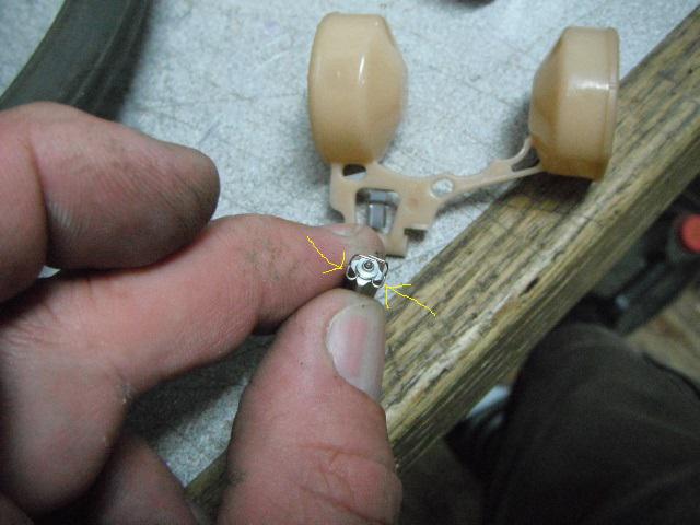
Next, I’ll install the float needles and floats. In the picture you’ll see the two hoops on the retainer. They get positioned facing the center “V†of the carb bank /and or / float pivot pin. This allows the retainer to sit deeper in the float tab for a more secure fitment. There is a special way these are positioned. If you get it wrong the retainer just barely contacts the end of the float tab. In my opinion, there is a chance for it to fall out.
Next, I’m going to set the float level. As with anything else, the float level is very important. All of mine measured different from the factory. Factory spec is 7mm. 3 of mine were at 8mm and one was at 9mm. Very lean emission settings. I set them all to 7mm. Equivalent to .275†if using a dial caliper.
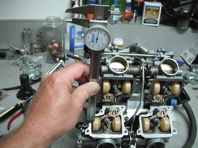
As seen in my pictures, the measurement gets taken from the side flat of the carb body to the outer top seam of the float. This is how the factory does it, and so do I. If adjustment is needed, I use a pick, and either bend the float tab up, or down, to get the correct measurement. I also have the carb bank tilted up, so the floats won’t depress the springs in the float needles. The needles are lightly seated to get an accurate measurement.
Next, I’ll install the float bowls. The bottom side is completely done!
Onto the top side, I’m going to check and see if my carbs have needle shims installed. Some ST’s do, some don’t. Depends upon the emission origin of the bike. After taking the needle’s out, mine have them. However, they are thinner and don’t measure consistently. I’m replacing with .020†Keihin aftermarket shim’s. This will allow the carb’s to get on the main circuit quicker in the mid-range rpm.
A #1 Phillips fit’s down in the needle retainer. This does not get un-screwed. It is a cam design. Turn the screw driver one click counterclockwise (about 45 degrees). The needle retainer will pop up and can be removed. If equipped with a shim, it will stick down in there. A longer pick, or a piece of wire will get the shim out. Reverse order for assembly.
Now that the needles are all set, I can finish assembling the top side. All of the slides / diaphragms, springs and covers go back in. I always have a good look around and see if I missed anything. If it all looks good, DONE !
#33
ST1100 Archive of Wisdom / Re: Carb Removal and Rebuild -...
Last post by KoTAOW - August 07, 2014, 06:12:36 PMCarb Removal and Rebuild ( ST1100 )
PART THREE:
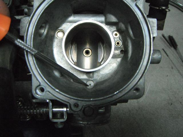
Now that the carbs are completely stripped and safe to clean, I prefer to do them outside for ventilation. I’m going to start with the topsides of the carbs. Spraying into every hole I see and blowing out with compressed air. All 3 of these vent holes go to something and serve a purpose. Make sure they’re free and clear.
Next, I move onto the diaphragm chamber area. Same goes here. All of these holes serve a purpose and need to be cleaned out with carb cleaner and compressed air. Vents for floats, choke, pilot and air-cut circuits.
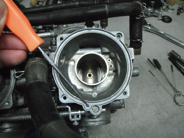
Next, I’ll move onto cleaning the air-cut valve passageways and plungers. Remember that this is also a part of the pilot / slow speed circuit and it controls the pilot mixture during deceleration.
This last picture is the air-cut plunger. I spray cleaner at it and move it in and out gently with a pick to make sure it’s not sticky. I also go easy with the compressed air.
All passageways and components are very important, and all of them work together. However, this is the most important part. The slow speed / pilot and transitional circuits are the first to get clogged and the hardest to clean, being so small in design by Keihin. These are the “first to goâ€. Keep in mind that the pilot circuit also supplies the idle mixture. If one goes, everything down line suffers.
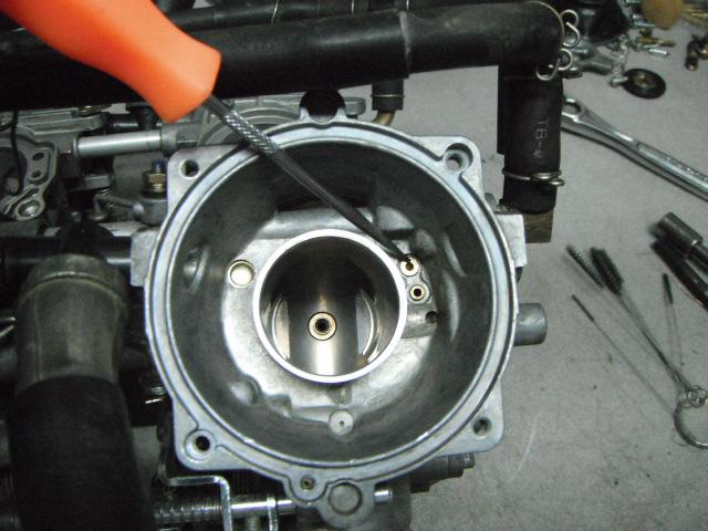
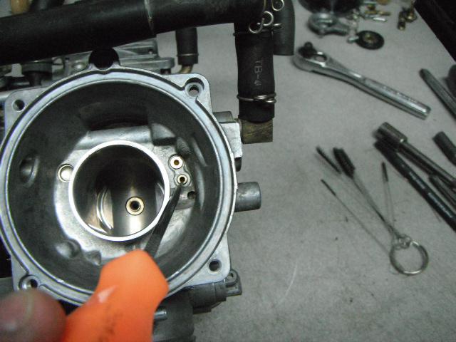
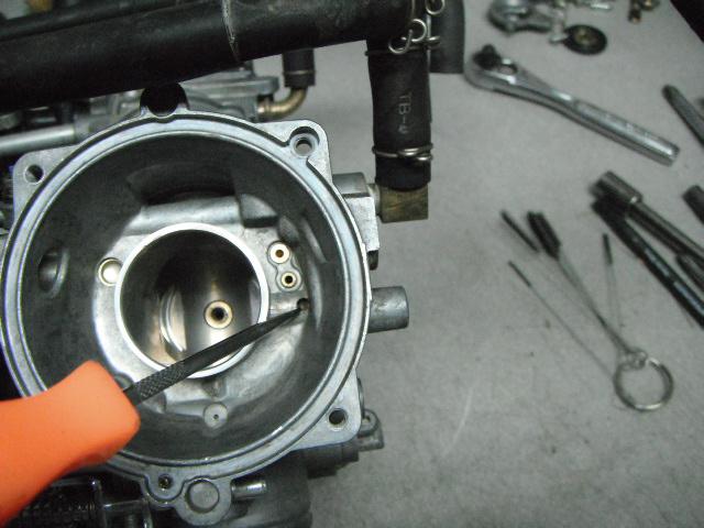
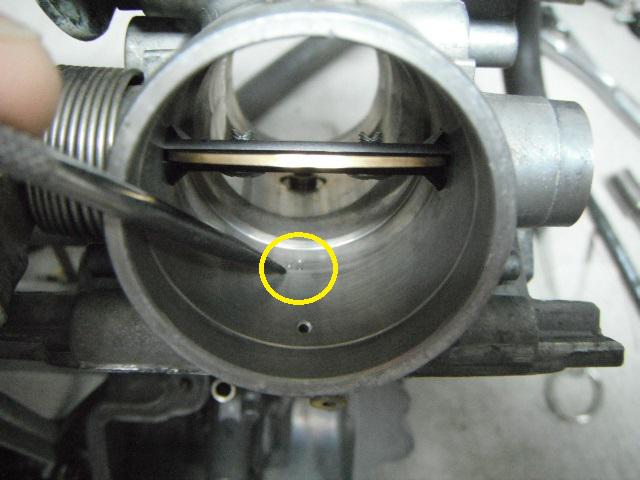
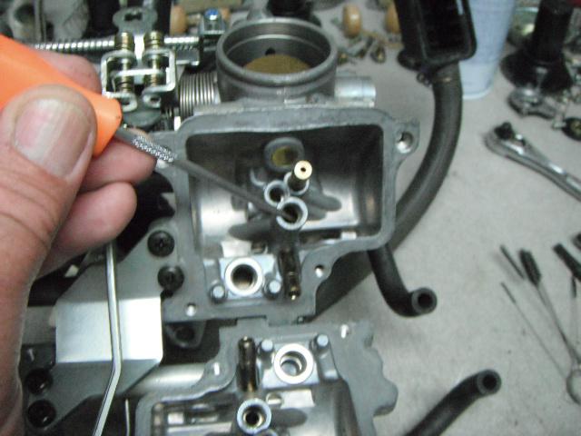
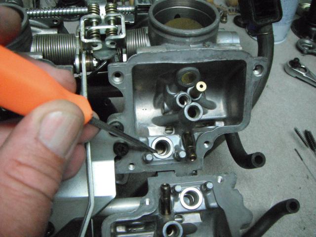
Back flush / spray out the idle mixture hole in the mouth of the carb. Then spray into the mixture screw hole. VERIFY that carb cleaner is coming out the other side and at a good stream. Blow them out with compressed air and continue to verify that passages are clear and a full stream of cleaner is coming out! It may be necessary to do multiple times.
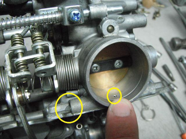
This next step is also critical. Get something to hold the throttle linkage wide open. Now I’m moving into the pilot circuit. I spray carb cleaner up into the pilot jet screw hole multiple times and look for it to come out of the idle mixture and the 3 little transitional slow speed / pilot holes at the throttle plate. VERIFY THAT CLEANER IS COMING OUT OF ALL 3 OF THOSE HOLES! Con pilot ports!
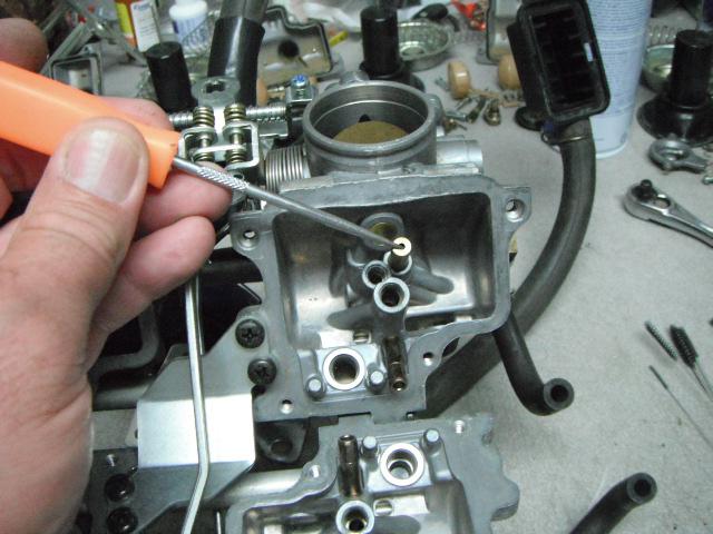
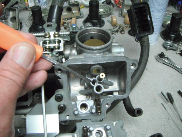
Next, I’ll flip the carb bodies over and spray out the choke / enriching supply(hold the choke open), pilot (again), main circuit, fuel bowl supply and upper half of bowl chamber. Verifying cleaner coming out the other ends with compressed air.
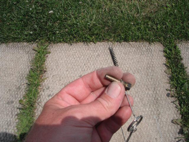
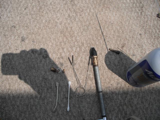
The carb bodies are now done and I’ll be moving onto the bowls, jets, etc. I always try to be creative when cleaning out these little jets, and pieces. Some may think it’s un-orthodox, but it’s quick, easy and gets the job done without ruining anything. Very small vinyl pipe cleaner set, Q-tips, small strands of copper wire, etc. I won’t be cleaning out the pilot jets, because I’m replacing with new ones (bigger #40 sized). Later I’ll be tuning the bike to pre-emission Canadian spec’s.
I always make sure all the little holes in the emulsion tubes are free and clear using cleaner and compressed air. The rest is pretty much self explanatory.
At this point, EVERYTHING has been cleaned and verified. I can now start assembling the carbs.
#34
ST1100 Archive of Wisdom / Re: Carb Removal and Rebuild- ...
Last post by KoTAOW - August 06, 2014, 04:14:23 PMCarb Removal and Rebuild ( ST1100 )
PART TWO:
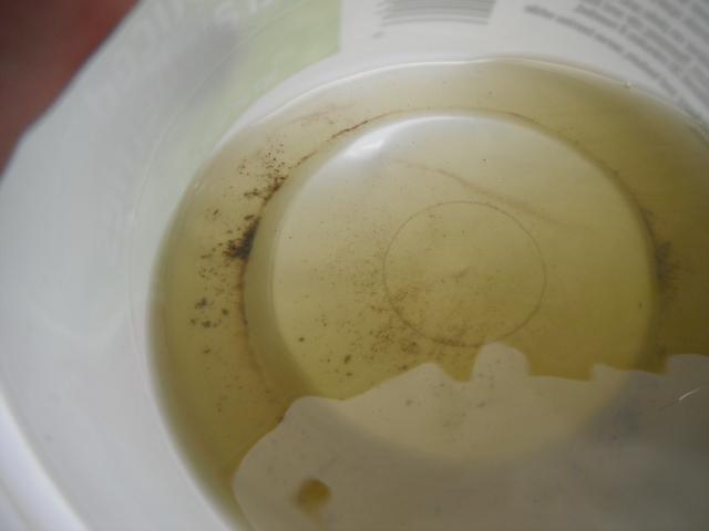
Now that the carbs are out, I always drain the float bowls into a clean container to see what, or if, anything comes out. I used the tailgate of the truck as a work bench to drain OUTSIDE in a well ventilated area. As you can see in my pic’s, the bowls are full of debris. Trouble....
The outsides of the carb bodies are filthy and need a good cleaning. Now is the time to do it. I used a whole can of carb cleaner and a blow gun / air compressor to clean them up. See the difference? Always start off with clean outsides so none of the junk gets into your cleaned carbs. Cleaning them will also help with the linkages, etc.
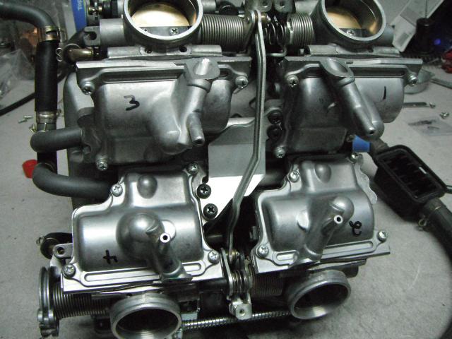
Now that the carbs are drained and cleaned, I can take them inside to the shop and start dis-assembly. First thing I’m going to do is mark EVERYTHING with it’s prospective cylinder #. Some thing’s I’m going to replace. Most of it will be returned to it’s original carb body, keeping all of the original factory mating surfaces the same. You’ll see I've also marked everything up top on the plenum and the intake snorkels. The top side is also coming off. Some guys don’t, but you’ll see why later-on that it’s best to remove it.
I started with taking off all of the float bowls. YUK! I’ve done countless carb rebuilds, but have never seen anything like this. Funny thing is, that the bike ran great, right up to the point to where it wouldn't.
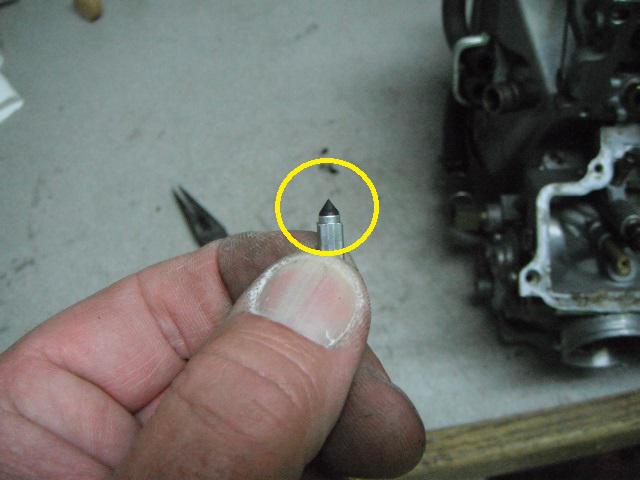
After the bowls are off, I removed all of the floats and checked to see if there was any leakage. Shaking them to see if there was any gas on the insides. All checked OK. I cleaned them and set them aside. I also took a real good look at the float needles. Many times the rubber tip gets worn and grooved. LOOK THEM OVER GOOD. If grooved, throw them away and get new needles and seats! Surprisingly, mine were OK and cleaned up well. I take a shop cloth and spray carb cleaner on the towel, then gently twist the tip of the needle in the cloth. Cleans them up well.
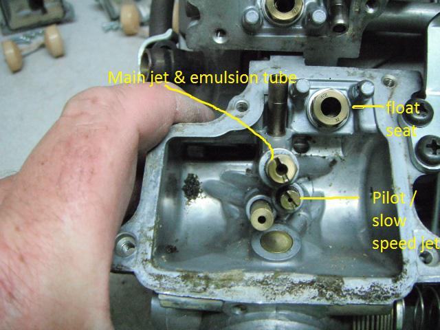
Next, I remove ALL of the jets. Float seats, idle mixture, slow speed / pilots, main jet and emulsion tube’s. Check the screens on the Float needle seats. Clean as needed. I have both a homemade idle mixture screw tool and a Honda factory tool. Homemade one gets used on the bench. I counted the screw turns from lightly seated. All were between 2 and 2 ½ turns from the factory. It doesn't matter to me what they are, because I will be doing a jet change and the idle drop procedure when done.


Now that all of the bottom side is disassembled, I’ll move to the top and take all of the upper components out. I start removing the diaphragm’s / slide’s and inspect the slides for wear. Also looking at the rubber diaphragm’s to see if they are in good shape, not torn, or dry and brittle. Mine checked out OK, but had some weird white stains on them. Probably from sitting for a long time. Most of it cleaned up. Also have a look at the needles to see if they are worn / scuffed from possibly rubbing.
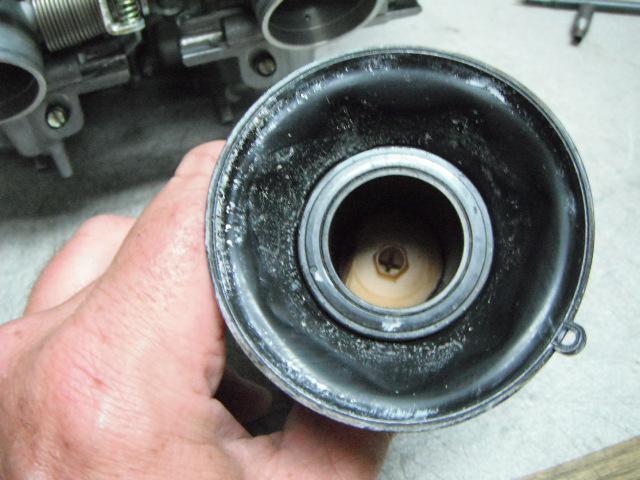
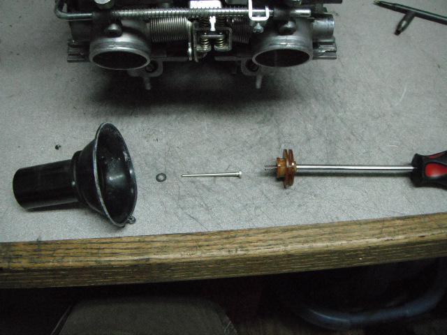
As you can see here, it is important to check and replace the secondary air breather filter regularly, just in front of the air cleaner assy. The breather filter on this bike disintegrated and filled the upper diaphragm chamber’s with foam filter material. Which also means particles went down into the carb vent, air-cut valve assy., choke vent and slow speed vent.
I now have a nice pile of carburetor parts. All numbered and placed separately with each corresponding cylinder number.
As mentioned earlier, some guys don’t take the upper plenum / tube assy. off when cleaning their carbs. It is relatively easy to remove it, but a pain to re-install. My opinion is that it must come off, or damage to the air-cut valve diaphragms, sooner or later, WILL happen. I've worked on quite a few bikes that were having fuel economy, idle speed, drivability and “running rich†conditions. All do to the “Shade Tree mechanic†destroying the air â€"cut valve diaphragms with carburetor cleaner, by NOT removing them. To get the air-cut valves out, the upper plenum must be removed.
Also take note that the plenum mounting screws are #3 Phillips. Using a #2 may work, but more than likely they will strip out. The screws are tight from the factory.
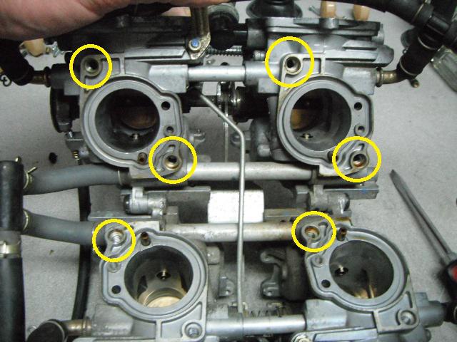
You’ll notice here that there are centering dowels on the bottom of the plenum. The screws go down through the center of them. Sometimes they fall out and get lost. Use caution when lifting up the plenum.
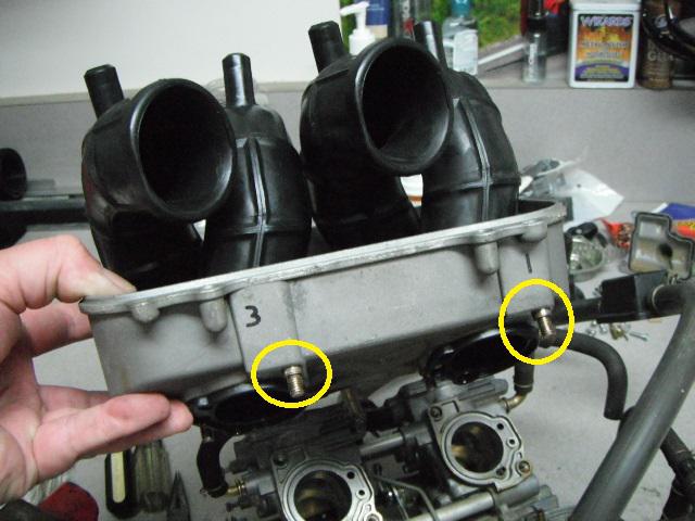
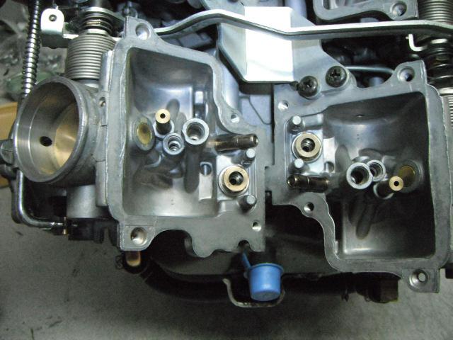
There are 8 dowels. I circled the locations in the carb bodies the best I could.
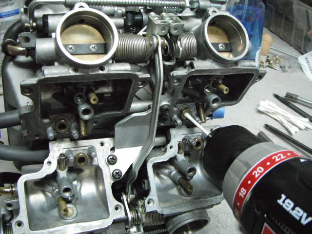
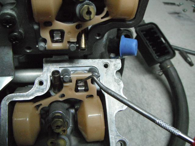
Now that the plenum is off, I can remove the air-cut valves. Sort of a challenging task, but can be done without breaking the carbs totally apart (major pain). I’ve taken the ST carbs totally apart once and vowed to never do it again! Linkages, springs, tubes, alignments, o-rings, etc.
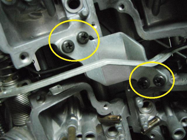
There are two valves facing on the outer bodies of the carb’s. I take them off first. Then move onto the inner ones.

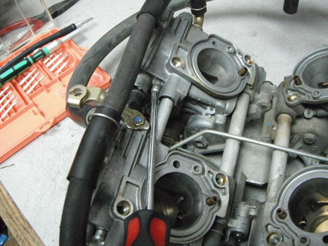
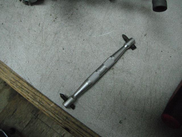
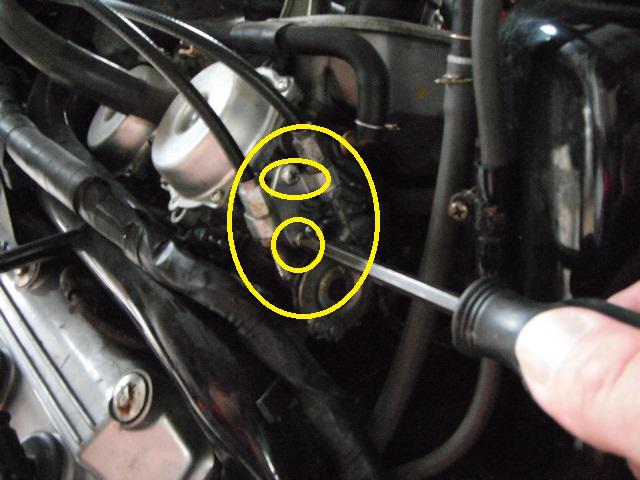
The inner valves upper screw can be removed with a #1 Phillips at an angle. Lots of inward pressure is needed so the screw doesn't strip, but breaks loose easily. For the lower screw, I use a 90 degree Phillips. Trust me, it can be done. I have to hold the throttle linkage out of the way for access. I used an old license plate wrench to hold the linkages open.
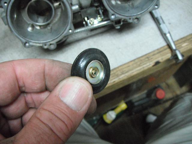
Check the diaphragms for dry rot, cracks, condition, etc... There are o-rings that will stick to the inner body of the carb. Don’t loose them...
I now have totally stripped carbs and ready for cleaning.
#35
ST1100 Archive of Wisdom / Carb Removal and Rebuild ( ST1...
Last post by KoTAOW - August 03, 2014, 09:33:44 AMSubmitted by Adam Frymoyer, STOC #949
~~~
PART ONE:
If your reading this, you’re probably in trouble with your carburetors. I hope you checked everything possible and performed a proper diagnosis before digging into this project. I’m a diesel engine builder by trade and have owned many bikes over the years. Primarily ST1100’s. I've also worked in a friends motorcycle / small engine dealership for a good number of years and have tuned, rebuilt and repaired everything under the sun. I've been doing this for a long time and hope that this will give some guidance on ST1100 carburetors. Remember that this is only a guide (and my opinion) to rebuilding ST carbs. My pictures and procedures may seem vague, but remember, this is only for a little re-assurance. Please follow the factory service manual for the proper way to work on your bike.
This particular bike, I acquired from an estate sale. I don’t know the history of the bike, other than it sat for a long time. The previous owner never took care of the bike and it sat in a shed for 4 years while his estate was settled. It started right up and I drove it home. Soft on power, but it ran good. With my busy schedule, it sat some more. Then the inevitable happened... The bike would fire right up, but only run on choke. The idle speed, slow speed and transitional circuits in the carbs were plugged. Time for a good carb cleaning and other maintenance while the carbs are out.
First things first, is to remove the bodywork needed to gain access to everything you will be doing. Seat, bags, top shelf, pocket panels and maintenance covers.
Next, will be removing air cleaner assembly.
Remove choke / enrichment cable and lay off to the left side of the bike.
At this point, some guys prefer to remove the fuel tank for easier access to the carbs. I never do. Just my opinion that it’s just more stuff to take apart and put back together.
Next will be loosening the upper carburetor isolator / boot clamps. I started with #3 only because I was on that side. (right rear carb) Use a brand new or a very good condition #2 Phillips screwdriver. Best to use a JIS driver if you have one, or purchase some early before you start. The screw heads are very soft and strip easily.
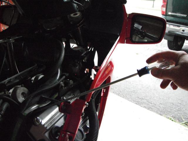
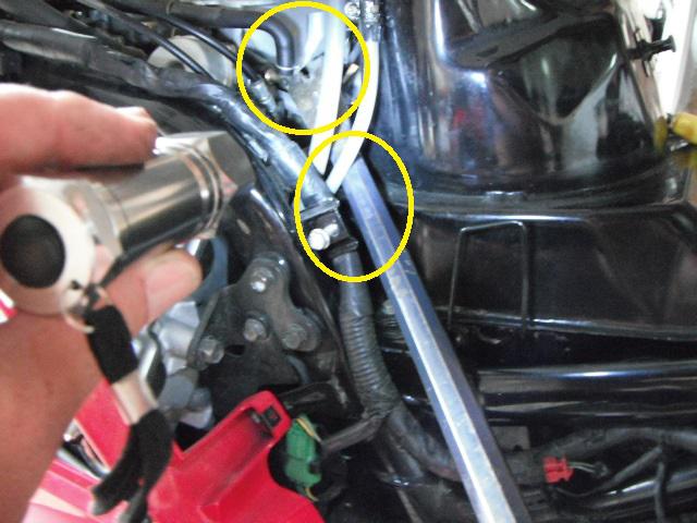
Next will be moving up to #1 carb. This is a tricky one. The clamp is usually loose and spun. It’s difficult to see and access. You may have to take another longer screw driver and rotate the clamp back into position to get at the Phillips screw head. I took the best pictures that I could, showing the angles of the driver and how to access. You’ll also have to move the coolant hose and wiring harness out of the way to get the driver down in there. You’ll also need a good bright flashlight to shine down from the top to see the screw head. As difficult as it seems, you should be in and out of there in less than 5 minutes.
After #1 is loose, I moved over to #2. Left front carb.
Then to #4, left rear. This one can be a little tricky too, getting the screwdriver between the frame and cylinder head. Again, use another driver to spin the clamp to get a good bite on the screw head.
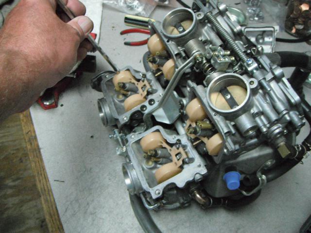
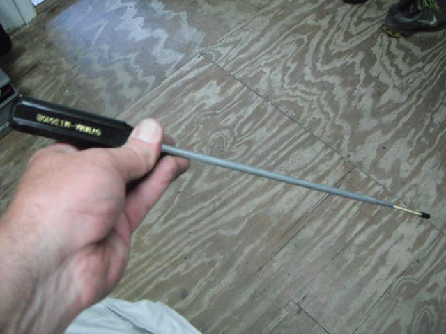
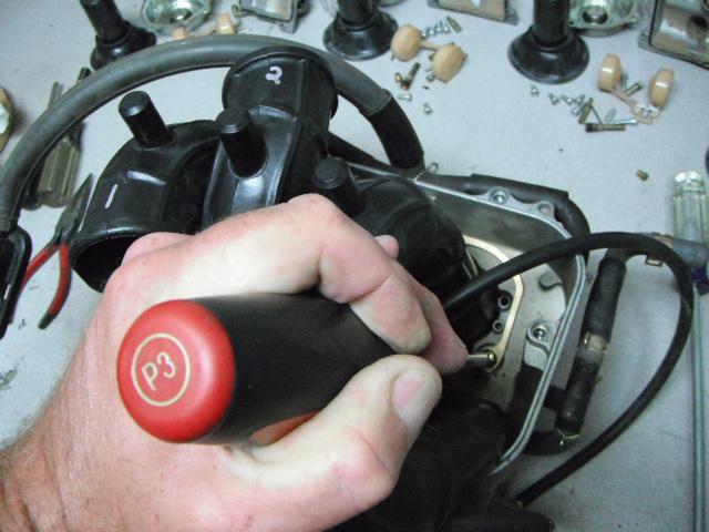
I’ve had this pry-bar for years, and it’s great for popping the carbs up and out of the boots. Don’t pry on the float bowls, linkages, etc. I pry “up†on the bottom of the plenum. Use the frame crossmember in front of the fuel tank to pry “down†on. Sometimes you’ll have to give it a good heave, but they’ll pop right out.
Next will be removing the throttle linkage. It’s best to wait until the carbs are popped up and loose, so you can get at the screws easier. The bottom screw is blocked with the carbs installed.
Then tilt the carb bank off to the right side and disconnect the float bowl drain hoses. You don’t have to slide the clamps down. The hoses will pull right off the nipples.
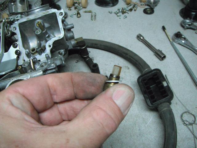
Disconnect the fuel supply hose from the vacuum / fuel shut down valve (if equipped). Just pull the hose going to the carbs. Leave everything else there to prevent fuel from spilling all over the place. Upon re-assy. I will be removing this valve and throwing it away.
After this is done also take the idle speed adjust cable and lay it over on top of the carbs now that the fuel lines are out of the way.
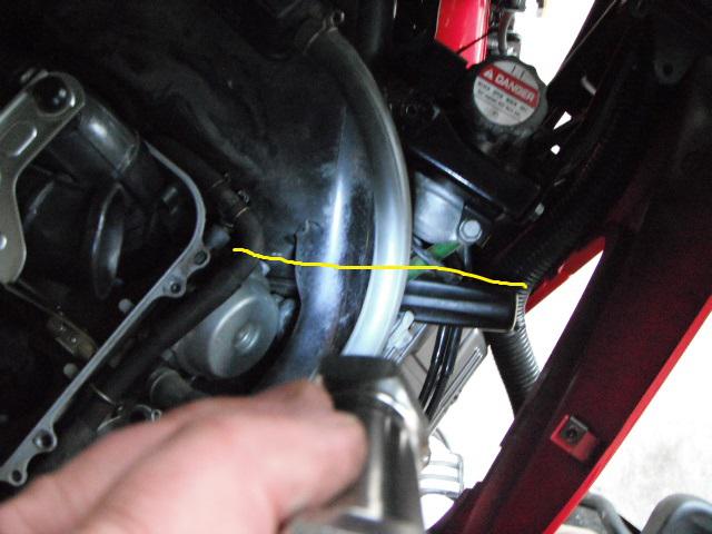
Move back around to the front of the carb bank, tilt the carbs upward and remove the fresh air intake hose going to the PAIR valves. You will more than likely have to cut it. The heat down in there welds / melts the rubber to the fitting. I had to cut mine.
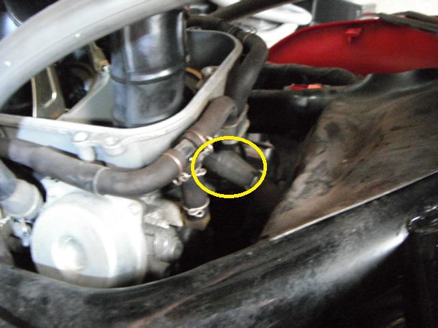
The carbs are totally disconnected at this time. Pull them out. See all the mouse pooh and pee down in there? I removed the rubber heat shield and cleaned. While the carbs were out, I also removed the PAIR valves and replaced all the coolant o-rings, seals, hoses and clamps. Something to strongly consider while you have everything out.


~~~
Carb Removal and Rebuild ( ST1100 )
PART ONE:
If your reading this, you’re probably in trouble with your carburetors. I hope you checked everything possible and performed a proper diagnosis before digging into this project. I’m a diesel engine builder by trade and have owned many bikes over the years. Primarily ST1100’s. I've also worked in a friends motorcycle / small engine dealership for a good number of years and have tuned, rebuilt and repaired everything under the sun. I've been doing this for a long time and hope that this will give some guidance on ST1100 carburetors. Remember that this is only a guide (and my opinion) to rebuilding ST carbs. My pictures and procedures may seem vague, but remember, this is only for a little re-assurance. Please follow the factory service manual for the proper way to work on your bike.
This particular bike, I acquired from an estate sale. I don’t know the history of the bike, other than it sat for a long time. The previous owner never took care of the bike and it sat in a shed for 4 years while his estate was settled. It started right up and I drove it home. Soft on power, but it ran good. With my busy schedule, it sat some more. Then the inevitable happened... The bike would fire right up, but only run on choke. The idle speed, slow speed and transitional circuits in the carbs were plugged. Time for a good carb cleaning and other maintenance while the carbs are out.
First things first, is to remove the bodywork needed to gain access to everything you will be doing. Seat, bags, top shelf, pocket panels and maintenance covers.
Next, will be removing air cleaner assembly.
Remove choke / enrichment cable and lay off to the left side of the bike.
At this point, some guys prefer to remove the fuel tank for easier access to the carbs. I never do. Just my opinion that it’s just more stuff to take apart and put back together.
Next will be loosening the upper carburetor isolator / boot clamps. I started with #3 only because I was on that side. (right rear carb) Use a brand new or a very good condition #2 Phillips screwdriver. Best to use a JIS driver if you have one, or purchase some early before you start. The screw heads are very soft and strip easily.
Next will be moving up to #1 carb. This is a tricky one. The clamp is usually loose and spun. It’s difficult to see and access. You may have to take another longer screw driver and rotate the clamp back into position to get at the Phillips screw head. I took the best pictures that I could, showing the angles of the driver and how to access. You’ll also have to move the coolant hose and wiring harness out of the way to get the driver down in there. You’ll also need a good bright flashlight to shine down from the top to see the screw head. As difficult as it seems, you should be in and out of there in less than 5 minutes.
After #1 is loose, I moved over to #2. Left front carb.
Then to #4, left rear. This one can be a little tricky too, getting the screwdriver between the frame and cylinder head. Again, use another driver to spin the clamp to get a good bite on the screw head.
I’ve had this pry-bar for years, and it’s great for popping the carbs up and out of the boots. Don’t pry on the float bowls, linkages, etc. I pry “up†on the bottom of the plenum. Use the frame crossmember in front of the fuel tank to pry “down†on. Sometimes you’ll have to give it a good heave, but they’ll pop right out.
Next will be removing the throttle linkage. It’s best to wait until the carbs are popped up and loose, so you can get at the screws easier. The bottom screw is blocked with the carbs installed.
Then tilt the carb bank off to the right side and disconnect the float bowl drain hoses. You don’t have to slide the clamps down. The hoses will pull right off the nipples.
Disconnect the fuel supply hose from the vacuum / fuel shut down valve (if equipped). Just pull the hose going to the carbs. Leave everything else there to prevent fuel from spilling all over the place. Upon re-assy. I will be removing this valve and throwing it away.
After this is done also take the idle speed adjust cable and lay it over on top of the carbs now that the fuel lines are out of the way.
Move back around to the front of the carb bank, tilt the carbs upward and remove the fresh air intake hose going to the PAIR valves. You will more than likely have to cut it. The heat down in there welds / melts the rubber to the fitting. I had to cut mine.
The carbs are totally disconnected at this time. Pull them out. See all the mouse pooh and pee down in there? I removed the rubber heat shield and cleaned. While the carbs were out, I also removed the PAIR valves and replaced all the coolant o-rings, seals, hoses and clamps. Something to strongly consider while you have everything out.
#36
ST1300 Archive of Wisdom / Replacing Garmin 2730 Touchscr...
Last post by KoTAOW - June 20, 2014, 06:12:50 AMSubmitted by Don Feyma, STOC #237
~~~
I finally got around to replacing the touchscreen digitizer in one of my 2730's this morning. All in all it was a pretty simple job. Paying attention to detail helps. Thought I'd take a few pictures along the way. I got involved and didn't take pics of some of the steps, so I'll try to get those when I replace the screen on my other 2730. I ended up with two of them when I bought for a pretty low price, another complete kit on closeout after my original screen went belly-up, so when the other replacement screen arrives I'll end up with two working 2730's. Yay!
UPDATE: I've now replaced the digitizer screen on the second 2730 and updated this post with the additional pictures. So, for about $48, I now have two seemingly brand new 2730's that are both working like new. Such a deal!
OK, so here's how it goes. Take your time and be patient and all will work out.
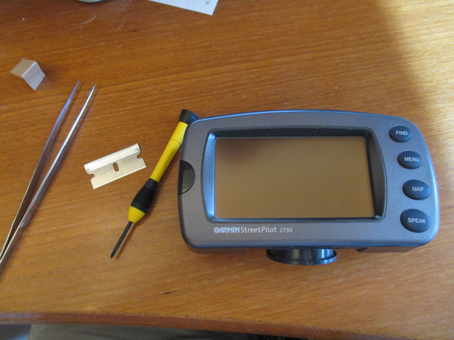
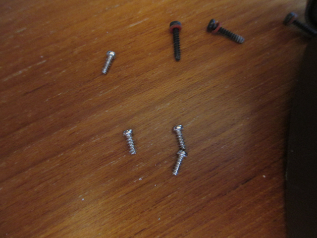
1. Here's what you'll need - 1 Garmin 2730 (or any in that family of 2600 and 2700's), a pair of tweezers, a single-side razor blade, preferably new and sharp, a small but not tiny precision phillips screwdriver. The size I used was size #0. You'll also need a new digitizer screen, available here: http://www.ebay.com/itm/261213216256?ssPageName=STRK:MEWNX:IT&_trksid=p3984.m1497.l2649
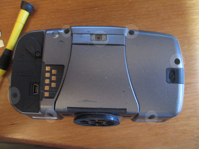
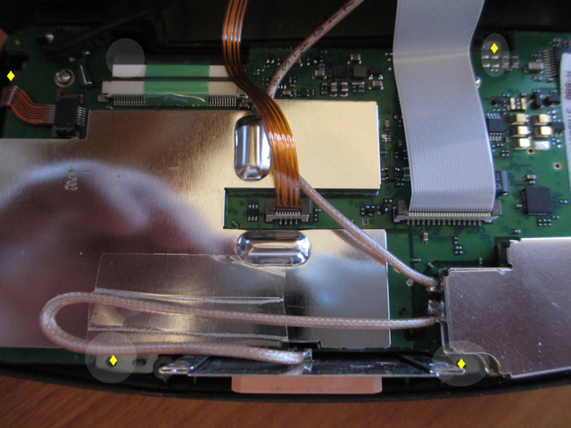
2. OK, first turn the gps over so it's screen down. Remove the 7 screws indicated by the shaded ovals in the next picture. They are difficult to remove from the holes, so just loosen them all the way so they're spinning. They have little rubber washers on them so they won't fall out easily.
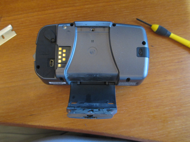
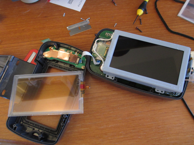
3. Flip the now-loose mounting base over - it'll remain attached to the front of the case.
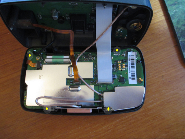
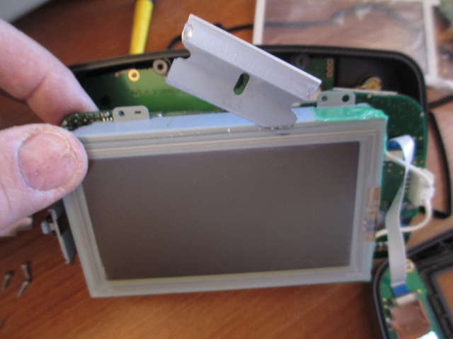
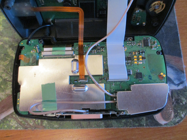
4. Using some patience, wiggle and tug the two case halves apart carefully. I wouldn't use a tool for fear of damaging the gasket. I used fingernails to help pry it apart. Set the back of the case up. There isn't any need to take any connectors off, there is enough slack to work with it. Now remove the four silver screws as indicated by YELLOW diamonds. They don't screw into the circuit board, they screw into some silver metal tabs.
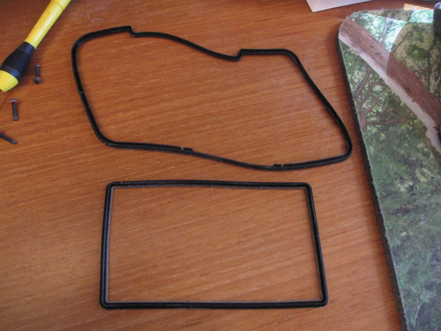
5. Turn the entire unit over, and you can push the guts out of the front cover from the front. There are two gaskets, the case gasket and the gasket that seals the screen. I took these off and carefully washed them with a little dish soap and water, and dried them. Set them aside for later, but try to remember the orientation of them front to back. I set them on the desk oriented with the front of the gasket toward the front of the screen, i.e. the upside goes toward the viewing side of the gps.
6. The metal thing with the square thing on top of the unit is the antenna. It's probably loose there and there is enough slack to move it aside. Do so, or if you have to, remove the tape from the wires and move it away. I didn't have to.
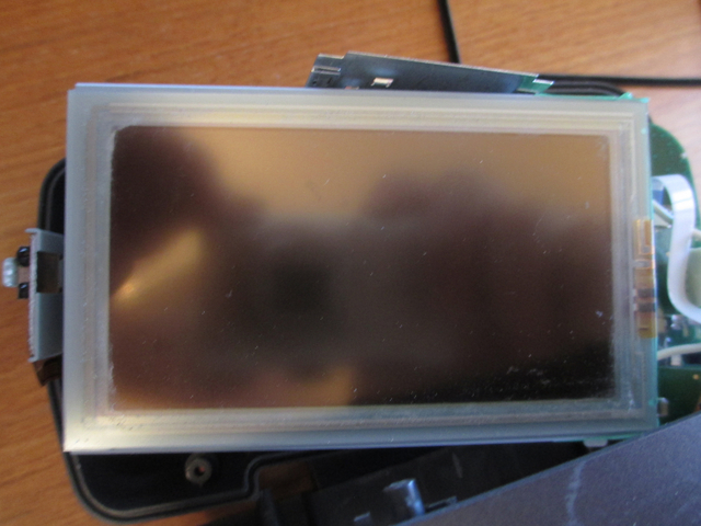
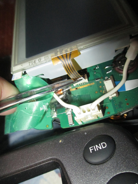
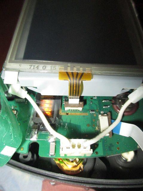
7. Carefully take off the piece of green tape covering the wires on the right side of the screen case and reserve it for later. Unplug the lead cable running from the old digitizer screen to the case. Here's where you use the tweezers, if you haven't already used it on the silver screws.
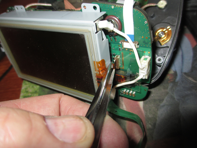
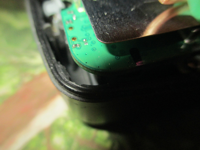
8. Then get out your razor blade and carefully and patiently cut the silicone glue that holds the old digitizer screen to the case. Take small passes and try not to cut your finger off.
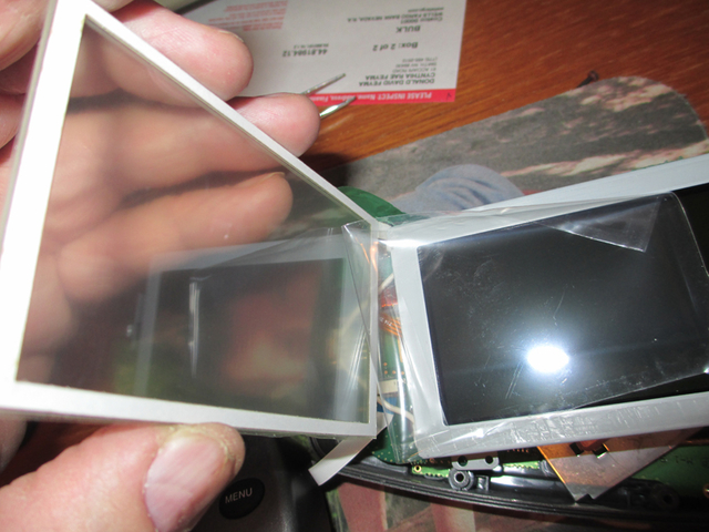
9. Using your tweezers, or your fingers if you have little girly hands, plug the lead cable of the new digitizer into the outlet on the case. I found that it was easiest to just lay the new screen in position and plug it in. It does take some force to plug in, and a magnifying glass doesn't hurt either.
10. Use some Dust-off, or whatever, to make sure there is no dust or dog hair or other debris on the the gps screen, then remove the protective film from the back of the new digitizer screen. Try not to get any fingerprints on the back of the digitizer screen or the video screen.
11. Remove the white liner from the adhesive strip on the back of the new digitizer and carefully line up the new digitizer screen and press into place. Replace the green tape over the wires.
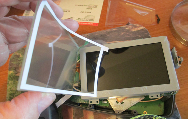
12. Remove the protective film from the front of the new digitizer screen. This part will be accessible for cleaning, so you don't need to worry as much about getting fingerprints on the front.
13. Put the screen gasket back in place in the slot provided on inside of the front case. If you lost the orientation for this, the ridge on the gasket goes toward the front outside of the unit.
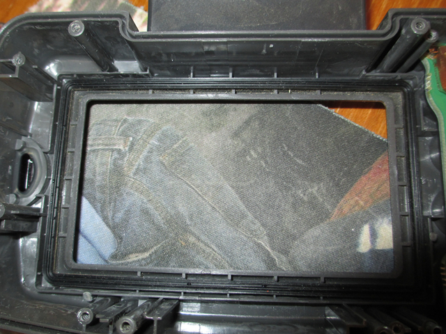
14. Press the unit back into the front of the case, making sure everything is seated correctly. Replace the four silver screws. Tighten but don't overtighten and strip the little tiny heads. This sucks if you do it.
15. Carefully replace the case gasket into the slot in the back of the case front. Fiddle with it until it's seated correctly. If you haven't already done so, make sure the antenna is correctly oriented at the top of the unit.
16. Replace the back of the unit and fasten the six black screws, again being careful not to overtighten and strip the heads out. Flip the tilt adjustment mechanism back over and re-tighten that screw.
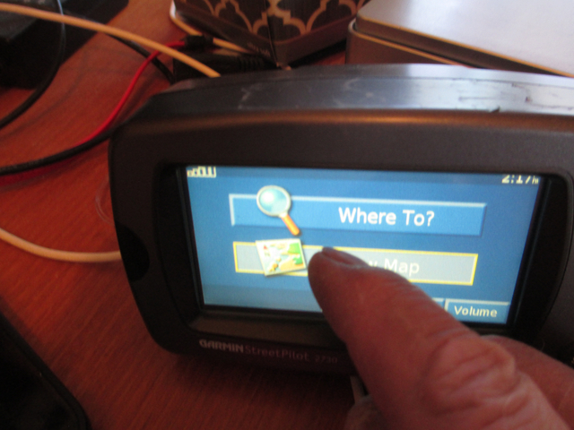
17. Plug in the gps, turn it on and enjoy your brand new unit!
~~~
Thank You again for your contribution Don Feyma, STOC #237
~~~
Replacing Garmin 2730 Touchscreen ( ST1100\ST1300 )
I finally got around to replacing the touchscreen digitizer in one of my 2730's this morning. All in all it was a pretty simple job. Paying attention to detail helps. Thought I'd take a few pictures along the way. I got involved and didn't take pics of some of the steps, so I'll try to get those when I replace the screen on my other 2730. I ended up with two of them when I bought for a pretty low price, another complete kit on closeout after my original screen went belly-up, so when the other replacement screen arrives I'll end up with two working 2730's. Yay!
UPDATE: I've now replaced the digitizer screen on the second 2730 and updated this post with the additional pictures. So, for about $48, I now have two seemingly brand new 2730's that are both working like new. Such a deal!
OK, so here's how it goes. Take your time and be patient and all will work out.
1. Here's what you'll need - 1 Garmin 2730 (or any in that family of 2600 and 2700's), a pair of tweezers, a single-side razor blade, preferably new and sharp, a small but not tiny precision phillips screwdriver. The size I used was size #0. You'll also need a new digitizer screen, available here: http://www.ebay.com/itm/261213216256?ssPageName=STRK:MEWNX:IT&_trksid=p3984.m1497.l2649
2. OK, first turn the gps over so it's screen down. Remove the 7 screws indicated by the shaded ovals in the next picture. They are difficult to remove from the holes, so just loosen them all the way so they're spinning. They have little rubber washers on them so they won't fall out easily.
3. Flip the now-loose mounting base over - it'll remain attached to the front of the case.
4. Using some patience, wiggle and tug the two case halves apart carefully. I wouldn't use a tool for fear of damaging the gasket. I used fingernails to help pry it apart. Set the back of the case up. There isn't any need to take any connectors off, there is enough slack to work with it. Now remove the four silver screws as indicated by YELLOW diamonds. They don't screw into the circuit board, they screw into some silver metal tabs.
5. Turn the entire unit over, and you can push the guts out of the front cover from the front. There are two gaskets, the case gasket and the gasket that seals the screen. I took these off and carefully washed them with a little dish soap and water, and dried them. Set them aside for later, but try to remember the orientation of them front to back. I set them on the desk oriented with the front of the gasket toward the front of the screen, i.e. the upside goes toward the viewing side of the gps.
6. The metal thing with the square thing on top of the unit is the antenna. It's probably loose there and there is enough slack to move it aside. Do so, or if you have to, remove the tape from the wires and move it away. I didn't have to.
7. Carefully take off the piece of green tape covering the wires on the right side of the screen case and reserve it for later. Unplug the lead cable running from the old digitizer screen to the case. Here's where you use the tweezers, if you haven't already used it on the silver screws.
8. Then get out your razor blade and carefully and patiently cut the silicone glue that holds the old digitizer screen to the case. Take small passes and try not to cut your finger off.
9. Using your tweezers, or your fingers if you have little girly hands, plug the lead cable of the new digitizer into the outlet on the case. I found that it was easiest to just lay the new screen in position and plug it in. It does take some force to plug in, and a magnifying glass doesn't hurt either.
10. Use some Dust-off, or whatever, to make sure there is no dust or dog hair or other debris on the the gps screen, then remove the protective film from the back of the new digitizer screen. Try not to get any fingerprints on the back of the digitizer screen or the video screen.
11. Remove the white liner from the adhesive strip on the back of the new digitizer and carefully line up the new digitizer screen and press into place. Replace the green tape over the wires.
12. Remove the protective film from the front of the new digitizer screen. This part will be accessible for cleaning, so you don't need to worry as much about getting fingerprints on the front.
13. Put the screen gasket back in place in the slot provided on inside of the front case. If you lost the orientation for this, the ridge on the gasket goes toward the front outside of the unit.
14. Press the unit back into the front of the case, making sure everything is seated correctly. Replace the four silver screws. Tighten but don't overtighten and strip the little tiny heads. This sucks if you do it.
15. Carefully replace the case gasket into the slot in the back of the case front. Fiddle with it until it's seated correctly. If you haven't already done so, make sure the antenna is correctly oriented at the top of the unit.
16. Replace the back of the unit and fasten the six black screws, again being careful not to overtighten and strip the heads out. Flip the tilt adjustment mechanism back over and re-tighten that screw.
17. Plug in the gps, turn it on and enjoy your brand new unit!
~~~
Thank You again for your contribution Don Feyma, STOC #237
#37
ST1100 Archive of Wisdom / Replacing Garmin 2730 Touchscr...
Last post by KoTAOW - June 20, 2014, 05:45:31 AMSubmitted by Don Feyma, STOC #237
~~~
I finally got around to replacing the touchscreen digitizer in one of my 2730's this morning. All in all it was a pretty simple job. Paying attention to detail helps. Thought I'd take a few pictures along the way. I got involved and didn't take pics of some of the steps, so I'll try to get those when I replace the screen on my other 2730. I ended up with two of them when I bought for a pretty low price, another complete kit on closeout after my original screen went belly-up, so when the other replacement screen arrives I'll end up with two working 2730's. Yay!
UPDATE: I've now replaced the digitizer screen on the second 2730 and updated this post with the additional pictures. So, for about $48, I now have two seemingly brand new 2730's that are both working like new. Such a deal!
OK, so here's how it goes. Take your time and be patient and all will work out.
1. Here's what you'll need - 1 Garmin 2730 (or any in that family of 2600 and 2700's), a pair of tweezers, a single-side razor blade, preferably new and sharp, a small but not tiny precision phillips screwdriver. The size I used was size #0. You'll also need a new digitizer screen, available here: http://www.ebay.com/itm/261213216256?ssPageName=STRK:MEWNX:IT&_trksid=p3984.m1497.l2649
2. OK, first turn the gps over so it's screen down. Remove the 7 screws indicated by the shaded ovals in the next picture. They are difficult to remove from the holes, so just loosen them all the way so they're spinning. They have little rubber washers on them so they won't fall out easily.
3. Flip the now-loose mounting base over - it'll remain attached to the front of the case.
4. Using some patience, wiggle and tug the two case halves apart carefully. I wouldn't use a tool for fear of damaging the gasket. I used fingernails to help pry it apart. Set the back of the case up. There isn't any need to take any connectors off, there is enough slack to work with it. Now remove the four silver screws as indicated by YELLOW diamonds. They don't screw into the circuit board, they screw into some silver metal tabs.
5. Turn the entire unit over, and you can push the guts out of the front cover from the front. There are two gaskets, the case gasket and the gasket that seals the screen. I took these off and carefully washed them with a little dish soap and water, and dried them. Set them aside for later, but try to remember the orientation of them front to back. I set them on the desk oriented with the front of the gasket toward the front of the screen, i.e. the upside goes toward the viewing side of the gps.
6. The metal thing with the square thing on top of the unit is the antenna. It's probably loose there and there is enough slack to move it aside. Do so, or if you have to, remove the tape from the wires and move it away. I didn't have to.
7. Carefully take off the piece of green tape covering the wires on the right side of the screen case and reserve it for later. Unplug the lead cable running from the old digitizer screen to the case. Here's where you use the tweezers, if you haven't already used it on the silver screws.
8. Then get out your razor blade and carefully and patiently cut the silicone glue that holds the old digitizer screen to the case. Take small passes and try not to cut your finger off.
9. Using your tweezers, or your fingers if you have little girly hands, plug the lead cable of the new digitizer into the outlet on the case. I found that it was easiest to just lay the new screen in position and plug it in. It does take some force to plug in, and a magnifying glass doesn't hurt either.
10. Use some Dust-off, or whatever, to make sure there is no dust or dog hair or other debris on the the gps screen, then remove the protective film from the back of the new digitizer screen. Try not to get any fingerprints on the back of the digitizer screen or the video screen.
11. Remove the white liner from the adhesive strip on the back of the new digitizer and carefully line up the new digitizer screen and press into place. Replace the green tape over the wires.
12. Remove the protective film from the front of the new digitizer screen. This part will be accessible for cleaning, so you don't need to worry as much about getting fingerprints on the front.
13. Put the screen gasket back in place in the slot provided on inside of the front case. If you lost the orientation for this, the ridge on the gasket goes toward the front outside of the unit.
14. Press the unit back into the front of the case, making sure everything is seated correctly. Replace the four silver screws. Tighten but don't overtighten and strip the little tiny heads. This sucks if you do it.
15. Carefully replace the case gasket into the slot in the back of the case front. Fiddle with it until it's seated correctly. If you haven't already done so, make sure the antenna is correctly oriented at the top of the unit.
16. Replace the back of the unit and fasten the six black screws, again being careful not to overtighten and strip the heads out. Flip the tilt adjustment mechanism back over and re-tighten that screw.
17. Plug in the gps, turn it on and enjoy your brand new unit!
~~~
Thank You again for your contribution Don Feyma, STOC #237
~~~
Replacing Garmin 2730 Touchscreen ( ST1100\ST1300 )
I finally got around to replacing the touchscreen digitizer in one of my 2730's this morning. All in all it was a pretty simple job. Paying attention to detail helps. Thought I'd take a few pictures along the way. I got involved and didn't take pics of some of the steps, so I'll try to get those when I replace the screen on my other 2730. I ended up with two of them when I bought for a pretty low price, another complete kit on closeout after my original screen went belly-up, so when the other replacement screen arrives I'll end up with two working 2730's. Yay!
UPDATE: I've now replaced the digitizer screen on the second 2730 and updated this post with the additional pictures. So, for about $48, I now have two seemingly brand new 2730's that are both working like new. Such a deal!
OK, so here's how it goes. Take your time and be patient and all will work out.
1. Here's what you'll need - 1 Garmin 2730 (or any in that family of 2600 and 2700's), a pair of tweezers, a single-side razor blade, preferably new and sharp, a small but not tiny precision phillips screwdriver. The size I used was size #0. You'll also need a new digitizer screen, available here: http://www.ebay.com/itm/261213216256?ssPageName=STRK:MEWNX:IT&_trksid=p3984.m1497.l2649
2. OK, first turn the gps over so it's screen down. Remove the 7 screws indicated by the shaded ovals in the next picture. They are difficult to remove from the holes, so just loosen them all the way so they're spinning. They have little rubber washers on them so they won't fall out easily.
3. Flip the now-loose mounting base over - it'll remain attached to the front of the case.
4. Using some patience, wiggle and tug the two case halves apart carefully. I wouldn't use a tool for fear of damaging the gasket. I used fingernails to help pry it apart. Set the back of the case up. There isn't any need to take any connectors off, there is enough slack to work with it. Now remove the four silver screws as indicated by YELLOW diamonds. They don't screw into the circuit board, they screw into some silver metal tabs.
5. Turn the entire unit over, and you can push the guts out of the front cover from the front. There are two gaskets, the case gasket and the gasket that seals the screen. I took these off and carefully washed them with a little dish soap and water, and dried them. Set them aside for later, but try to remember the orientation of them front to back. I set them on the desk oriented with the front of the gasket toward the front of the screen, i.e. the upside goes toward the viewing side of the gps.
6. The metal thing with the square thing on top of the unit is the antenna. It's probably loose there and there is enough slack to move it aside. Do so, or if you have to, remove the tape from the wires and move it away. I didn't have to.
7. Carefully take off the piece of green tape covering the wires on the right side of the screen case and reserve it for later. Unplug the lead cable running from the old digitizer screen to the case. Here's where you use the tweezers, if you haven't already used it on the silver screws.
8. Then get out your razor blade and carefully and patiently cut the silicone glue that holds the old digitizer screen to the case. Take small passes and try not to cut your finger off.
9. Using your tweezers, or your fingers if you have little girly hands, plug the lead cable of the new digitizer into the outlet on the case. I found that it was easiest to just lay the new screen in position and plug it in. It does take some force to plug in, and a magnifying glass doesn't hurt either.
10. Use some Dust-off, or whatever, to make sure there is no dust or dog hair or other debris on the the gps screen, then remove the protective film from the back of the new digitizer screen. Try not to get any fingerprints on the back of the digitizer screen or the video screen.
11. Remove the white liner from the adhesive strip on the back of the new digitizer and carefully line up the new digitizer screen and press into place. Replace the green tape over the wires.
12. Remove the protective film from the front of the new digitizer screen. This part will be accessible for cleaning, so you don't need to worry as much about getting fingerprints on the front.
13. Put the screen gasket back in place in the slot provided on inside of the front case. If you lost the orientation for this, the ridge on the gasket goes toward the front outside of the unit.
14. Press the unit back into the front of the case, making sure everything is seated correctly. Replace the four silver screws. Tighten but don't overtighten and strip the little tiny heads. This sucks if you do it.
15. Carefully replace the case gasket into the slot in the back of the case front. Fiddle with it until it's seated correctly. If you haven't already done so, make sure the antenna is correctly oriented at the top of the unit.
16. Replace the back of the unit and fasten the six black screws, again being careful not to overtighten and strip the heads out. Flip the tilt adjustment mechanism back over and re-tighten that screw.
17. Plug in the gps, turn it on and enjoy your brand new unit!
~~~
Thank You again for your contribution Don Feyma, STOC #237
#38
ST1100 Archive of Wisdom / Re: Hondaline Topcase Latch/Lo...
Last post by John OoSTerhuis - March 18, 2014, 04:12:34 PMRIP Don.
In the USA, as of Mar 2014, it looks like Motomachines carries carries the Hepco latches. Looks to be one of these:
http://www.motomachines.com/Latch-Assy-lid-to-case_p_706.html
http://www.motomachines.com/Latch-Assy-lid-to-case_p_707.html
Regards, John
In the USA, as of Mar 2014, it looks like Motomachines carries carries the Hepco latches. Looks to be one of these:
http://www.motomachines.com/Latch-Assy-lid-to-case_p_706.html
http://www.motomachines.com/Latch-Assy-lid-to-case_p_707.html
Regards, John
#39
ST1300 Archive of Wisdom / Homemade Jumper Cables with Qu...
Last post by KoTAOW - January 08, 2013, 09:04:55 PM* * * Article pending permission by Author * * *
Submitted by T_C, STOC #XXXX
Original article can be found here:
www.st-owners.com
~~~
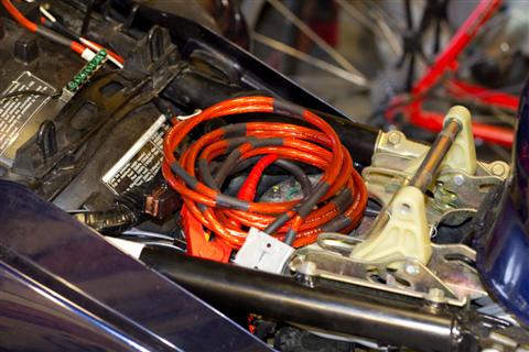
Homemade Jumper Cables with Quick Connect ( ST1300 )
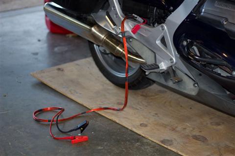
Pair of homemade jumper cables and a quick disconnect on the bike side. After reading some of the horror stories and knowing the ST does not have the biggest reserve capacity, thought it best to be safe. Also did not want to get stuck with having the key in the ignition and not being able to put stuff away, so these I can just throw about anywhere. One time I had to get jumped when I was riding a Virago. Big pain in the rump there as you had to remove the battery to get to both terminals and then you had to disconnect a lead to slide it back in. Not again!
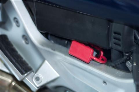
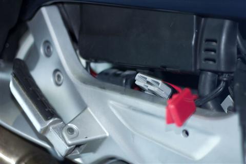
Used an Anderson PowerPole sbs50 for the quick connect. 50 amp continuous rating and the price was right (free). Had them leftover from some UPS battery packs. You can pick them up for $6 or so I do believe, one of the shops by me has 'em. Should be enough to handle a quick charge or the momentary surge of a starter. Left the end attached to the bike right under the battery box, used a boot on the back side and a dust cover on the front. Used a foot long piece of line fused at 80 amp for the hot, 6 gauge return is straight to the battery also.
With the dust cover open:
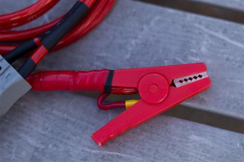
Clamps were from Wally land, marine world. Surprisingly good from what I can tell. Hopefully the plastic won't get brittle in cold. Will have to wait and see on that one I guess. The contacts on the inside were for only a 1/4" quick connect terminal. Not quite enough to handle a good solid high amp draw in my opinion. I soldered the main wire direct to one of the sides, then used the 1/4 quick connects to run a 12 gauge wire from one side of the clamp to the other. This will give both jaws some share of the power and assures a better electrical contact. You can see the wire between the handle in the picture. The mains were given some strain relief by using heat shrink to attach them to the handles of the clamps.
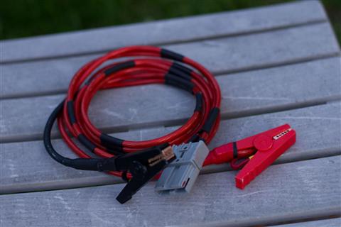
Wire is some 8 gauge, 80 amp fuse is housed right next to the battery. 6 foot long should give me enough room to get to where I can get in a place to yell CONTACT.
The overall bundle is pretty small. You will most surely notice that I used red wire for both positive and negative. Well, that was all I could find at a decent price. So the negative lead has a black piece of heat shrink every 6 inches and the last 6 inches of the wire next to the clamp are covered in black also.
Stowed under the seat they are ready for use. I think I need to get a Crown Royal bag to put them in. Nothing ruins a day like a dead battery, nothing makes a day like a little purple bag? Well hopefully they will be ready and available if I ever see anything cute needing a hand, or maybe anyone else too.
Keep the rubber side down and lend a hand when someone needs it...
Good day.
~~~
Thank You again for your contribution T_C, STOC #XXXX
#40
ST1300 Archive of Wisdom / Re: (Stickie) AOW article pict...
Last post by Tom Melnik - January 08, 2013, 09:40:06 AMUpdate:
I have tagged each AOW article with a single * at the end of the title for the articles that I have successfully recovered the pictures or did not have any attached pictures.
Any article tagged with double **, means there are still missing pictures from other sources, other than Webshots.
I have tagged each AOW article with a single * at the end of the title for the articles that I have successfully recovered the pictures or did not have any attached pictures.
Any article tagged with double **, means there are still missing pictures from other sources, other than Webshots.