- Welcome to ST-Riders - The liST.

The Original ST1100/ST1300 Forum
News:
Welcome to the liST! Before Posting, READ the liST rules stickie post Here! This is a private, STOC-members-only forum. Your real name and STOC# must appear in all posts. Failure to comply with these rules may result in your profile being changed, your account being suspended and/or your posts being removed.
Recent posts
#61
ST1300 Archive of Wisdom / TrailTech MR16 Driving Lights ...
Last post by KoTAOW - April 09, 2012, 10:47:53 AMSubmitted by John Herring, aka JohnnyRide
Original article can be found here: TrailTech MR16 Driving Lights
~~~

You will want to install a dedicated power harness w/relay along with this setup to protect the factory relays and wiring of your investment. The PIAAs come with everything you need including a harness and relay with other connectors as well but if you picked up a used pair without any other parts then see this Gadget page as there isn't much point in me rewriting anything on that. Adaptable relay harnesses are always available from sources such as Pepboys®, Walmart® and, Autozone®, to name a few. Usually around $20.
These are the TrailTech MR-16 Lamps Dichroic output pattern which are MR-16 based lights. Unlike the Silver Bullets out there, they can actually be pointed where you want the light to go and they are more waterproofed than the Silver Bullets as well. This company also sells their MR16 HID lights which I would have bought if they could start up quicker than 20 seconds. On hilly curvy roads the ability to turn off lights for on coming traffic and then turn them right back on it a priority. The HIDS just won't come right back on, you wait 20 seconds and that ruled them out for me. Now for other type roads, this isn't that important such as straight highways out in the middle of no where. Anyway, I am off target here, back to what I bought.

You can go with a low voltage bulb or you can go up to a 75W, like me. Construction is really good on these and at an affordable price which, are 1/2 the MSRP of THE PIAA 1100X lights and the replacement bulbs are mucho cheaper as well.
The front rings screws off and reveals he large black rubber weather ring which also doubles as a anti shock ring for the bulb.


Trailtech lights being designed for off road use hard wire their bulbs so you can't just unplug the bulb from a socket when you need to quickly replace the bulb. I suggest you get a couple of the small MR16 Sockets and solder them in to the circuit so bulb replacement isn't a nightmare at the wrong time.

Once mounted, they look very nice considering I mounted them up-side-down.
I have the 75W, 12 degree spot in the housing currently but They really ought to be wider for Tennessee hilly back roads at speed. I think they do a better jobs than the PIAAs hands down. I got a hold of some 24 degree bulbs and some 35 degree bulbs and think I like the 35 degree bulbs the best. They really aren't driving lights they are most effective in a 100-150 foot range. So don't expect Hella FF50 performance. I have found that it is best to point the lights out to about 10:00 and 2:00 for the a good all around settting. If i get into tighter curves and so forth I would tilt them up a little so when I lean the are then pointing straighter, if you know what I mean.

You can also see how the mount on the light case can be adjusted left to right and up and down for that perfectly positioned beam of salvation.


Here is a source for the MR16 socket I spoke of and a source for replacement bulbs.
D2758 Ceramic Bi-Pin Halogen Socket 2 $2.98
Ceramic Bi-Pin Halogen Socket
Rated 100W-250V
G5.3/GX5.3
10" Leads
Light Bulbs Etc, Inc.
~~~
Thank You again for your contribution John Herring, aka JohnnyRide
Original article can be found here: TrailTech MR16 Driving Lights
~~~
TrailTech MR16 Driving Lights ( ST1300 )
You will want to install a dedicated power harness w/relay along with this setup to protect the factory relays and wiring of your investment. The PIAAs come with everything you need including a harness and relay with other connectors as well but if you picked up a used pair without any other parts then see this Gadget page as there isn't much point in me rewriting anything on that. Adaptable relay harnesses are always available from sources such as Pepboys®, Walmart® and, Autozone®, to name a few. Usually around $20.
These are the TrailTech MR-16 Lamps Dichroic output pattern which are MR-16 based lights. Unlike the Silver Bullets out there, they can actually be pointed where you want the light to go and they are more waterproofed than the Silver Bullets as well. This company also sells their MR16 HID lights which I would have bought if they could start up quicker than 20 seconds. On hilly curvy roads the ability to turn off lights for on coming traffic and then turn them right back on it a priority. The HIDS just won't come right back on, you wait 20 seconds and that ruled them out for me. Now for other type roads, this isn't that important such as straight highways out in the middle of no where. Anyway, I am off target here, back to what I bought.
You can go with a low voltage bulb or you can go up to a 75W, like me. Construction is really good on these and at an affordable price which, are 1/2 the MSRP of THE PIAA 1100X lights and the replacement bulbs are mucho cheaper as well.
The front rings screws off and reveals he large black rubber weather ring which also doubles as a anti shock ring for the bulb.
Trailtech lights being designed for off road use hard wire their bulbs so you can't just unplug the bulb from a socket when you need to quickly replace the bulb. I suggest you get a couple of the small MR16 Sockets and solder them in to the circuit so bulb replacement isn't a nightmare at the wrong time.
Once mounted, they look very nice considering I mounted them up-side-down.
I have the 75W, 12 degree spot in the housing currently but They really ought to be wider for Tennessee hilly back roads at speed. I think they do a better jobs than the PIAAs hands down. I got a hold of some 24 degree bulbs and some 35 degree bulbs and think I like the 35 degree bulbs the best. They really aren't driving lights they are most effective in a 100-150 foot range. So don't expect Hella FF50 performance. I have found that it is best to point the lights out to about 10:00 and 2:00 for the a good all around settting. If i get into tighter curves and so forth I would tilt them up a little so when I lean the are then pointing straighter, if you know what I mean.
You can also see how the mount on the light case can be adjusted left to right and up and down for that perfectly positioned beam of salvation.
Here is a source for the MR16 socket I spoke of and a source for replacement bulbs.
D2758 Ceramic Bi-Pin Halogen Socket 2 $2.98
Ceramic Bi-Pin Halogen Socket
Rated 100W-250V
G5.3/GX5.3
10" Leads
Light Bulbs Etc, Inc.
~~~
Thank You again for your contribution John Herring, aka JohnnyRide
#62
ST1300 Archive of Wisdom / Reducing Leg Heat ( ST1300 ) *
Last post by KoTAOW - April 09, 2012, 10:12:39 AMSubmitted by John Herring, aka JohnnyRide
Original article can be found here: Reducing Leg Heat
~~~
This is the simplest and quickest way to reduce the heat you may feel on your legs. If the exiting of engine heat from the sides of the fairing don't bother you, you still may want to read this. The heat I feel coming off the sides of the faring is most noticeable when the outside air is around 75-90 degrees Fahrenheit. The basic design of the cowling is to pull and control the air on the front of the bike so that it is funneled through the radiator. The problem arises when the air, which just went through the 200 degree+ radiator, continues through the radiator and then is somehow suppose to assist in cooling off the engine. Since the bike is water cooled, I have decided that Honda never intended the incoming air to cool any thing other than the radiator. Therefore the water cooling will take care of the engine. So since all that nice hot air is being jammed inside the engine compartment, the exiting of that air through the side cut outs on the fairing rolls out on your legs. I think the air comes in faster than it exits when you are riding. I could be nuts but lets move on.
So if we add additional air intake paths to the engine, we should have cooler results overall.
The easiest way is to remove the two inner cowls. It is really easy to do. The first thing to do is remove the 2 center push plastic rivets from the top sides of the 2 storage compartments.
Simply push the centers of these plastics pin gently. They should move 1/16th of an inch or so. Next, work your fingernails under the edges and pull them out. They should come out easily if you have pushed the centers in enough.
Looking under front of the fairing, you will need to remove four more plastic rivets and 1 screw per side. Once you remove the front right side, move to the left side.
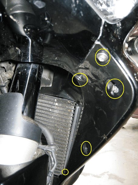
The picture has yellow circles which indicate what you need to remove.
When you pulling the cowl out, watch out for the radiator fins as they are way too easy to hit and damage.
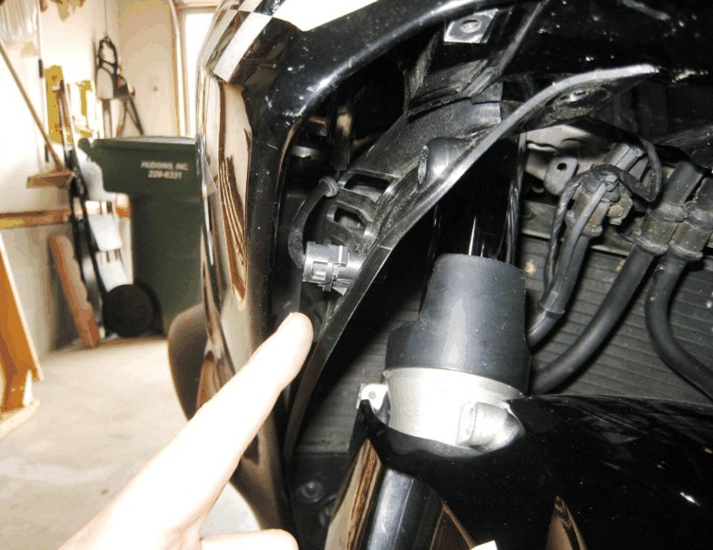
The left side comes off the same as the other. Be aware the air temperature sensor is incorporated into this side. You will need to partially remove the cowling so that you can remove 1 screw which retains the sensor. The finger points to the sensor.
The yellow square in the picture below shows the new location of the sensor. I used a tie anchor and a tie wrap.
The red square is the mounted piece of cowling from the picture below.
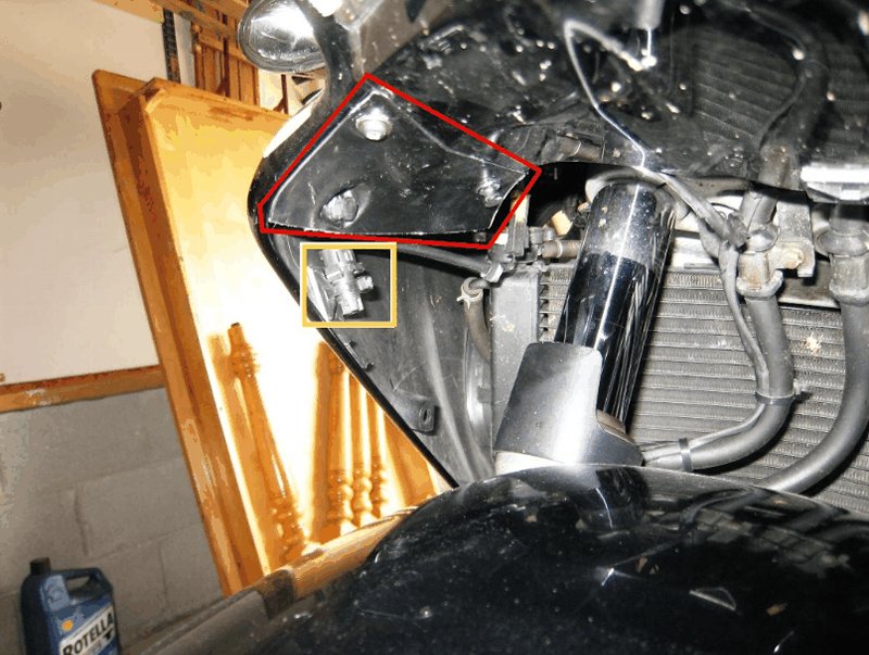
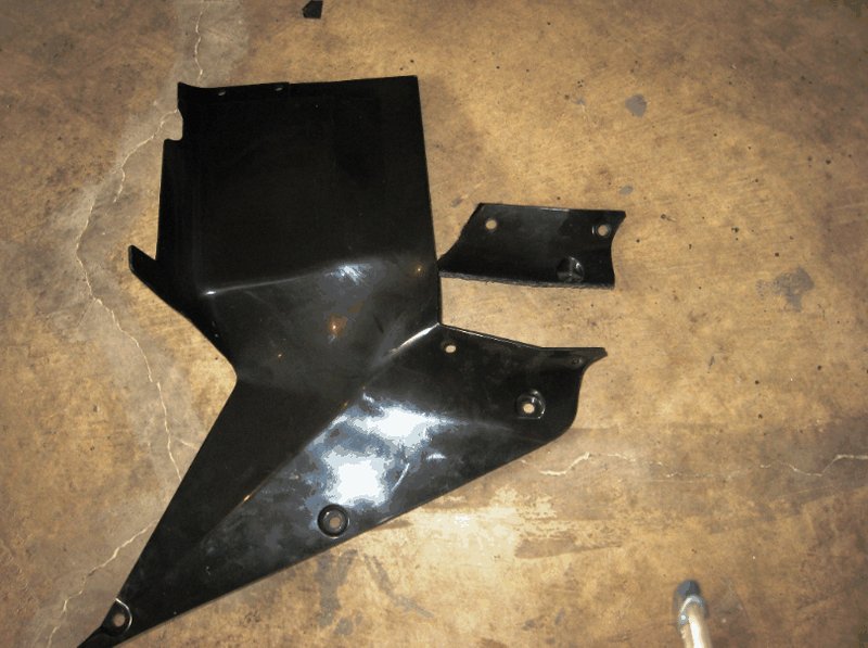
I wanted the added bracing, or at least a portion of the support the inner cowling provided to the fairing, so I cut out the corner of the inner cowl for this purpose. This gives me three mounting points. This is optional as I really don't think it makes a big difference other than you will have to buy replacement units at some point.
Now as a side benefit of this easy mod, I have noticed that the bike handling has improved. I have noticed that crosswinds don't seem to make the bike dive into the wind like it use to. I also feel that some of the effects of turbulence you experience around trucks , SUV and square shaped camping trailers is reduced. The bike feels less jittery under these conditions as compared to with the cowlings installed. Since more air is able to move though the fairing, incoming air is not trapped inside the fairing for as long and exits quicker. I also think the additional airflow which does not directly pass through the radiator helps dissipate the heat which builds up under the gas tank and seat. The good thing about this mod is that you can put the cowlings back in during colder weather.
~~~
Thank You again for your contribution John Herring, aka JohnnyRide
Original article can be found here: Reducing Leg Heat
~~~
Reducing Leg Heat ( ST1300 )
This is the simplest and quickest way to reduce the heat you may feel on your legs. If the exiting of engine heat from the sides of the fairing don't bother you, you still may want to read this. The heat I feel coming off the sides of the faring is most noticeable when the outside air is around 75-90 degrees Fahrenheit. The basic design of the cowling is to pull and control the air on the front of the bike so that it is funneled through the radiator. The problem arises when the air, which just went through the 200 degree+ radiator, continues through the radiator and then is somehow suppose to assist in cooling off the engine. Since the bike is water cooled, I have decided that Honda never intended the incoming air to cool any thing other than the radiator. Therefore the water cooling will take care of the engine. So since all that nice hot air is being jammed inside the engine compartment, the exiting of that air through the side cut outs on the fairing rolls out on your legs. I think the air comes in faster than it exits when you are riding. I could be nuts but lets move on.
So if we add additional air intake paths to the engine, we should have cooler results overall.
The easiest way is to remove the two inner cowls. It is really easy to do. The first thing to do is remove the 2 center push plastic rivets from the top sides of the 2 storage compartments.
Simply push the centers of these plastics pin gently. They should move 1/16th of an inch or so. Next, work your fingernails under the edges and pull them out. They should come out easily if you have pushed the centers in enough.
Looking under front of the fairing, you will need to remove four more plastic rivets and 1 screw per side. Once you remove the front right side, move to the left side.
The picture has yellow circles which indicate what you need to remove.
When you pulling the cowl out, watch out for the radiator fins as they are way too easy to hit and damage.
The left side comes off the same as the other. Be aware the air temperature sensor is incorporated into this side. You will need to partially remove the cowling so that you can remove 1 screw which retains the sensor. The finger points to the sensor.
The yellow square in the picture below shows the new location of the sensor. I used a tie anchor and a tie wrap.
The red square is the mounted piece of cowling from the picture below.
I wanted the added bracing, or at least a portion of the support the inner cowling provided to the fairing, so I cut out the corner of the inner cowl for this purpose. This gives me three mounting points. This is optional as I really don't think it makes a big difference other than you will have to buy replacement units at some point.
Now as a side benefit of this easy mod, I have noticed that the bike handling has improved. I have noticed that crosswinds don't seem to make the bike dive into the wind like it use to. I also feel that some of the effects of turbulence you experience around trucks , SUV and square shaped camping trailers is reduced. The bike feels less jittery under these conditions as compared to with the cowlings installed. Since more air is able to move though the fairing, incoming air is not trapped inside the fairing for as long and exits quicker. I also think the additional airflow which does not directly pass through the radiator helps dissipate the heat which builds up under the gas tank and seat. The good thing about this mod is that you can put the cowlings back in during colder weather.
~~~
Thank You again for your contribution John Herring, aka JohnnyRide
#63
ST1300 Archive of Wisdom / Speedohealer Installation ( ST...
Last post by KoTAOW - April 09, 2012, 09:23:07 AMSubmitted by John Herring, aka JohnnyRide
Original article can be found here: Speedohealer Installation
~~~

Price ( April 2012 ): $114.99
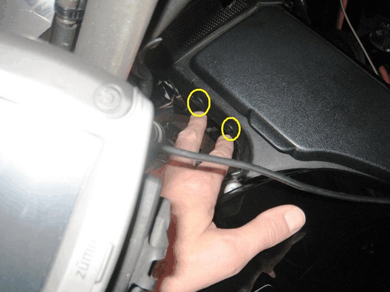
Like every vehicle out there, the Nomad is no different in the fact that your speedometer tells you are going faster than you really are. My VW Jetta is off is 6% off, my wife's Toyota is off and so is my daughter's car. I noticed an option on one manufacturers page that sells a speedo which is extremely accurate and the face of the speedo slows a little line for each MPH. Oh, and that's under the Law Enforcement Equipment options. Well it's nice to know the Police know how fast they are going. Well I like most people want to know WTF I am doing with regards to speed. I discovered that I was 8% off on my ST1300 speedo. That's a lot to me and that won't get it. So, enter the Speedo Healer, a nice little device to correct that error. It is reasonably easy to install and the folks at HealTech Electronics have a handy little on-line calculator to tell you how to program the Speedohealer when you know how far off you are. The instruction which are available on Speedo's Web site are satisfactory. I found that the actual installation of the plugs required moving the an engine component to be able to get to the 3P Black Speed Sensor Plug.
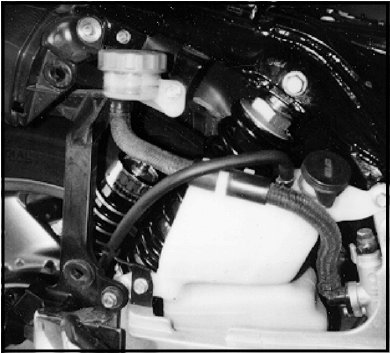
The finger points to the location of the dust boot which contains 3 different plugs, one of which is the Black Speedo Sensor Plug. Do you see it yet? Me neither As you can see, things are in the way.

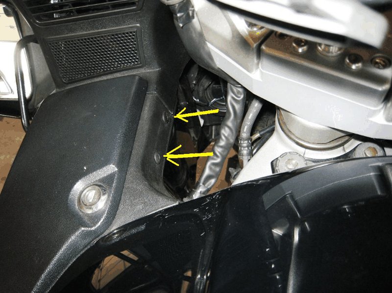
Remove these two bolts....

Move this out of the way and you can pull the harness up enough to plug in the needed plugs. You need to find your own way to route the orange harness to its new home. I selected the top of the battery cover. Getting there is half the fun. Once you there and have it all squared away, follow the remaining instructions provided my the manufacturer. Check out their web site as well for the Calculator which will tell you the procedure for programming the unit.

~~~
Thank You again for your contribution John Herring, aka JohnnyRide
Original article can be found here: Speedohealer Installation
~~~
Speedohealer Installation ( ST1300 )
Price ( April 2012 ): $114.99
Like every vehicle out there, the Nomad is no different in the fact that your speedometer tells you are going faster than you really are. My VW Jetta is off is 6% off, my wife's Toyota is off and so is my daughter's car. I noticed an option on one manufacturers page that sells a speedo which is extremely accurate and the face of the speedo slows a little line for each MPH. Oh, and that's under the Law Enforcement Equipment options. Well it's nice to know the Police know how fast they are going. Well I like most people want to know WTF I am doing with regards to speed. I discovered that I was 8% off on my ST1300 speedo. That's a lot to me and that won't get it. So, enter the Speedo Healer, a nice little device to correct that error. It is reasonably easy to install and the folks at HealTech Electronics have a handy little on-line calculator to tell you how to program the Speedohealer when you know how far off you are. The instruction which are available on Speedo's Web site are satisfactory. I found that the actual installation of the plugs required moving the an engine component to be able to get to the 3P Black Speed Sensor Plug.
The finger points to the location of the dust boot which contains 3 different plugs, one of which is the Black Speedo Sensor Plug. Do you see it yet? Me neither As you can see, things are in the way.
Remove these two bolts....
Move this out of the way and you can pull the harness up enough to plug in the needed plugs. You need to find your own way to route the orange harness to its new home. I selected the top of the battery cover. Getting there is half the fun. Once you there and have it all squared away, follow the remaining instructions provided my the manufacturer. Check out their web site as well for the Calculator which will tell you the procedure for programming the unit.
~~~
Thank You again for your contribution John Herring, aka JohnnyRide
#64
ST1100 Archive of Wisdom / Works Shock Mounting Instructi...
Last post by KoTAOW - April 07, 2012, 04:51:57 PMWorks Shock Mounting Instructions ( ST1100 )

Works Performance Products, Inc.
21045 OsBorne Street, Canoga Park, CA 91304
818.701.1010 Fax 818.701.9043
sales@worksperformance.com
21045 OsBorne Street, Canoga Park, CA 91304
818.701.1010 Fax 818.701.9043
sales@worksperformance.com
CAUTION: This shock is pressurized to 250 psi nitrogen. The pressure is not an adjustable feature of the shock. Unless the reservoir bladder assembly leaks, the shock should not normally lose pressure. If, after an extended period of time or number of miles, the damping becomes soft or mushy, the shock may need to be serviced which includes shock oil and a nitrogen charge. In this situation, re-pressurizing the shock alone may not improve the action of the shock. The shock should be returned to Works Performance Products, Inc. or to a qualified shop that has the appropriate tools, training and nitrogen handling equipment.
SHOCK TYPES
Works Performance Products, Inc. constructs two types of shocks for the ST1100. Both have an integral reservoir (often referred to as a “piggyback†reservoir). This reservoir increases the shock fluid capacity. This additional fluid helps dissipate heat generated by the damping in the shock. The reservoir contains a polyurethane bladder which separates the nitrogen from the shock oil. The shocks differ in the external adjustments.
RACER
The Racer shock features a large 1.375†damping piston and Works’ exclusive check-ball and orifice damping system. This damping system allows an extremely wide range of damping through the high-, medium- and low-speed circuits that are incorporated in the design. It has spring pre-load adjustment to change the ride height to accommodate changing loads.
PRO RACER
The Pro Racer shock features a twin tube design with external compression and rebound adjustments. This design also incorporates an orifice damping system, one that is unique to Works Performance. This damping system allows an extremely wide range of adjustments to the high-, medium- and low-speed circuits on compression and rebound. it has spring pre-load adjustment to change the ride height to accommodate changing loads. (Damping adjustment information is contained in an additional instruction sheet that comes with the Pro Racer series of shocks.)
INSTALLATION
1. Place the motorcycle on the center stand. Remove the seat and the right side panel from the motorcycle.
2. Remove the lower shock mounting bolt first. A wedge may be needed under the rear tire to free the bolt. The swingarm will drop at this point.
3. Remove the top shock bolt and withdraw the shock towards the rear of the motorcycle.
4. Make sure that the two-piece bushings are in place in each of the eyelets of the Works Performance shock.
NOTE: Do not try to install the shock with only one half of the bushing set, as this will lead to poor performance and remature seal leakage. For the same reasons, do not grind or file the inner or outer edges of the bushing to make them narrower. The amount of “float†in the bushing set is necessary to ensure smooth operation of the damper assembly.
FIG. 1: ST1100 SHOCK MOUNTING ORIENTATION. SHAFT POINTS UP AND RESERVOIR IS TO THE REAR.
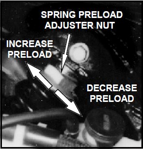
5. The shock mounts with the reservoir towards the rear of the motorcycle and at the bottom of the shock. This means that the shock shaft will point up and the threaded post and large preload nut will be accessible at the top.
6. Install the shock eye in the upper mounting channel. Install the mounting bolt and nut finger tight.
7. Pull the shock towards the rear of the motorcycle and raise the swingarm to engage the lower shock eye. The rear wheel wedge will be helpful here. The shock body can be twisted in either direction to line up the bushings with the channel, should it not be oriented exactly in line.
8. Install the lower shock mounting bolt and nut.
9. Sparingly apply a thread locking compound to the threads on the shock mounting fasteners, and tighten the lower fastener to 18 to 22 lbs/ft, and the upper fastener to 12 to 16lbs/ft. If there is an excessive amount of play between the lower shock bushing and the bolt, it may be wear on the bolt itself. In this design, the bolt is used as a bearing surface, and as a result can become undersized with time. The replacement bolt is Honda # 90159-MG9-000
FIG. 2: WASHER PLACEMENT UNDER HEAD OF BRAKE RESERVOIR ATTACHMENT BOLT
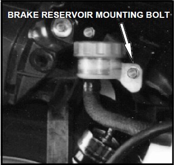
10. Install one or more (as necessary) of the 6mm flat washers supplied with the shocks under the head of the bolt that secures the brake master cylinder reservoir to the frame (Fig. 2). Ideally, the end of the bolt should be flush with the captured nut on the frame. In some cases the bolts are longer than necessary and will contact the edge of the shock reservoir when the shock is fully bottomed.
CHECKING RIDE HEIGHT
1. Place the seat in position so that the rider can sit on the bike. Leave the side panel off so that you can access the preload nut on the shock.
2. With the bike still on the stand, have an assistant measure the distance from a point on the rear axle to a point on the frame directly above it. Record this measurement.
3. Take the bike off the center stand, and have the rider bounce on the suspension a few times and then let the bike settle. With the rider still in place, have the assistant measure between the same two points on the axle and frame. Subtract the second measurement from the first. For the stock length shock, the difference should be between 1-1/4 inches (minimum) to 1-5/8 inches (maximum). (The short shock range is 3/4 inch to 1 inch.) If it falls within this range, no adjustment is necessary.
4. If it is less than the minimum, unscrew the nut about one turn. (These adjustments are most easily made with the bike on the center stand.) Check the measurement again by repeating Steps 1 - 3.
5. If the measurement exceeds the maximum, screw the nut down about one turn. Check the measurement again by repeating Step 13. Continue to adjust as necessary to achieve the correct ride height.
6. To adjust for the additional weight of a passenger, turn the nut down enough turns to restore the bike to the correct ride height. Once you have done this once, remember the number of turns you made so you can quickly make the changes before a ride.
7. Replace seat and side panel.
FIG. 3: ADJUSTING SPRING PRELOAD WITH THE ADJUSTER NUT.
~~~
PDF version is attached below.
#65
ST1100 Archive of Wisdom / Tip Over Wing LED's ( ST1100 )...
Last post by KoTAOW - April 06, 2012, 03:34:01 PMSubmitted by Terry Huusko, aka AZ711, STOC #7592
Original article can be found here: ST1100 - Tip-Over Wing LED's
~~~
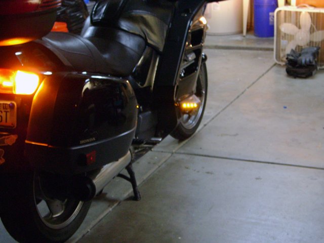
A couple of months back, my brother-in-law found instructions on line for installing LED’s on the tip-over wings on his BMW 1200LT. These LED’s would function as running lights and also operate in “wig-wag†fashion with the stock turn signals. We went ahead and installed those, and both of us were quite pleased with the results.
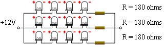
I have taken those instructions (which can be found here) and used them as a guide to install LED’s on my ST1100 tip-over wings. I used the template the document supplies on page 18 for the layout of 16 3mm yellow LED’s. Because BMW uses a two wire turn signal/running lights configuration, compared to the three wire configuration used by the ST, I configured the forward facing 12 LED’s to operate as running lights, and the rearward facing 4 LED’s as turn signal indicators. Additionally, I also made two other variations from the instructions for my installation. Instead of using a load resistor on each LED, I used this LED Calculator to configure the parallel/series circuits shown below.
12-LED Layout
4-LED Layout

~~~
Approximately $20.00 in parts required for both sides.
Additional Part Information:
Yellow LED's Qty. 1-9 $0.60 each 10-99 $0.54 each
The RL3-Y4545 is 3mm through hole LED. This yellow LED has a wavelength of 588nm at a millicandela rating of 4,500mcd.
It has a 45 degree viewing angle with a clear lens.
16 LED's needed per side.
180 ohm, 1/4 Watt Resistor's Package of 25 $1.65 each
The QW118-25 NTE is a metal film, flameproof resistor, 1/4 Watt, 180 ohm, 2%, axial lead.
4 RESISTOR's needed per side.
~~~
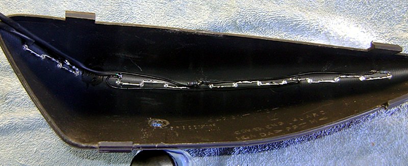
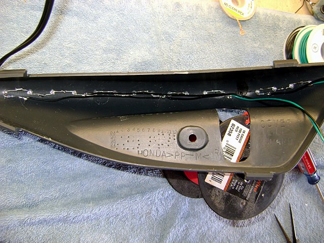
Also, instead of filling the tip-over wing with silicon for insulating purposes, I used Silicone Conformal Coating. Using the conformal coating would allow for easier removal and repair if an LED or two should happen to fail.
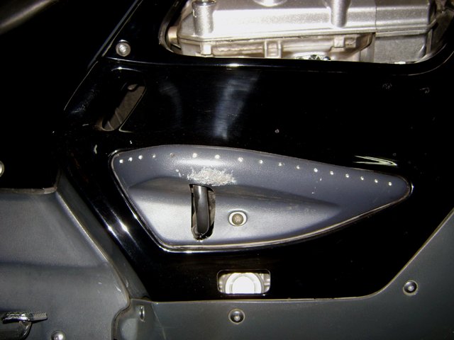
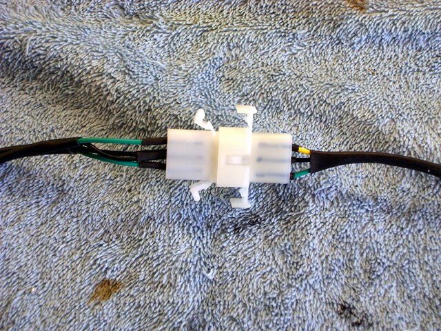
After installing the LED’s in the tip-over wings, I used three pin (1-running lights, 2-turn signal, 3-ground) male/female Molex connectors for the disconnect needed to remove the tip-over wings from the bike. I installed shrink tubing on the wires and routed them along the frame, following the factory wiring harness, and made the final connections at the front, mirror mounted turn signals.
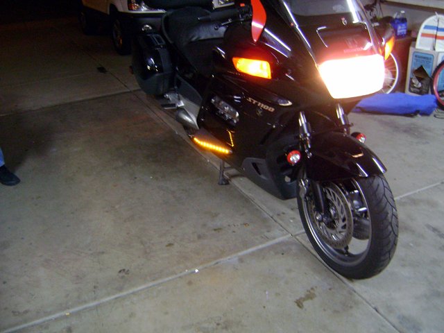
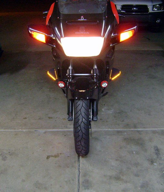
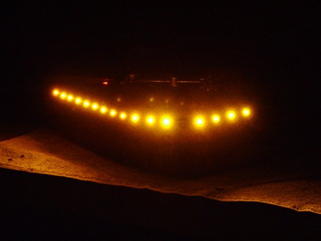
Below are some photos showing the various stages of the installation and the final result. Please feel free to contact me for any additional information or questions you may have. Also, if there is anyone out there who would like to do this, but is uncertain of their soldering skills, please drop me a PM and I would be happy to work out a way that I could assist you.

~~~
Thank You again for your contribution Terry Huusko, aka AZ711, STOC #7592
Original article can be found here: ST1100 - Tip-Over Wing LED's
~~~
Tip Over Wing LED's ( ST1100 )
A couple of months back, my brother-in-law found instructions on line for installing LED’s on the tip-over wings on his BMW 1200LT. These LED’s would function as running lights and also operate in “wig-wag†fashion with the stock turn signals. We went ahead and installed those, and both of us were quite pleased with the results.
I have taken those instructions (which can be found here) and used them as a guide to install LED’s on my ST1100 tip-over wings. I used the template the document supplies on page 18 for the layout of 16 3mm yellow LED’s. Because BMW uses a two wire turn signal/running lights configuration, compared to the three wire configuration used by the ST, I configured the forward facing 12 LED’s to operate as running lights, and the rearward facing 4 LED’s as turn signal indicators. Additionally, I also made two other variations from the instructions for my installation. Instead of using a load resistor on each LED, I used this LED Calculator to configure the parallel/series circuits shown below.
12-LED Layout
4-LED Layout
~~~
Approximately $20.00 in parts required for both sides.
Additional Part Information:
Yellow LED's Qty. 1-9 $0.60 each 10-99 $0.54 each
The RL3-Y4545 is 3mm through hole LED. This yellow LED has a wavelength of 588nm at a millicandela rating of 4,500mcd.
It has a 45 degree viewing angle with a clear lens.
16 LED's needed per side.
180 ohm, 1/4 Watt Resistor's Package of 25 $1.65 each
The QW118-25 NTE is a metal film, flameproof resistor, 1/4 Watt, 180 ohm, 2%, axial lead.
4 RESISTOR's needed per side.
~~~
Also, instead of filling the tip-over wing with silicon for insulating purposes, I used Silicone Conformal Coating. Using the conformal coating would allow for easier removal and repair if an LED or two should happen to fail.
After installing the LED’s in the tip-over wings, I used three pin (1-running lights, 2-turn signal, 3-ground) male/female Molex connectors for the disconnect needed to remove the tip-over wings from the bike. I installed shrink tubing on the wires and routed them along the frame, following the factory wiring harness, and made the final connections at the front, mirror mounted turn signals.
Below are some photos showing the various stages of the installation and the final result. Please feel free to contact me for any additional information or questions you may have. Also, if there is anyone out there who would like to do this, but is uncertain of their soldering skills, please drop me a PM and I would be happy to work out a way that I could assist you.
~~~
Thank You again for your contribution Terry Huusko, aka AZ711, STOC #7592
#66
ST1100 Archive of Wisdom / Re: Fuel Pump Repair ( ST1100 ...
Last post by KoTAOW - April 05, 2012, 02:21:34 PMComments by Norm Keller, STOC#8030
The manual is not of much help for testing of many components, pump included. A pump diagnosis should include volume measurements, pressure test (dead head pressure) and current draw.
A good pump delivers delivers 1 liter in less than 35 seconds dead-head pressure 2 PSI and draws 0.9 amps. which was the comparison on which I based the theory or commutator issues.
A poorly performing pump is typically in the 0.7 amp range from a 12.5 volt source (a battery without running engine). IME, this is the most reliable test of a pump's condition providing that inlet and outlet are not restricted by something such as a plugged filter.
I recommend testing current by jumping the pump directly to battery power in order to measure outlet volume and current flow. This can be done with the pump in place and is part of my periodic PM testing, and something which might be considered by others in order to try to anticipate problems.
A subsequent test of pump current with the pump connected to the bike's wiring should indicate a similar current flow, otherwise there is excessive resistance in the bike's wiring/components.
Most of the pumps I have seen have not had significant commutator damage and have only required use of crocus cloth to clean the coating (appears to be a lacquer or varnish) from the contact surface of the brushes and commutator sections..
Rather than cutting the case as suggested by John, I pry the case tabs back to allow the end housing to be withdrawn. This allows the tabs to be pushed back into place during reassembly, this making the assembly appear as original. Which ever technique most appeals should be equally successful.
Inspect the pressure relief (by-pass) valve as sticking or material holding the valve open allows loss of pump output and reduces both volume & pressure while showing a normal current flow.
I continue to search for failed pumps as test mules and would appreciate contact with someone who has a poorly performing pump and would be willing to try some experiments. I would like to explore the removal of varnish/lacquer by use of some solvent such as Sea Foam® or, failing that type of product, a diluted lacquer thinner or other more aggressive material.
I have repaired several of these pumps as well as alternators, ABS Modulators and other components.
Good job on the post, John Hudson, aka GitSum, STOC #8086. It may be quite useful for someone needing to do this work.
~~~
Thank You for your contribution Norm Keller, STOC#8030
#67
ST1100 Archive of Wisdom / Fuel Pump Repair ( ST1100 ) *
Last post by KoTAOW - April 04, 2012, 04:59:08 PMContributed by John Hudson, aka GitSum, STOC #8086
~~~
Here is how I was able to revive my OEM pump.
I originally took it apart to just see how it worked, but the only thing wrong with it that I could find was that it was
pretty well "crudded up"
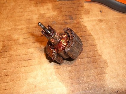
First of all - this is what the armature and magnets looked like once I pulled it apart! Geez, I wonder why it stopped working!
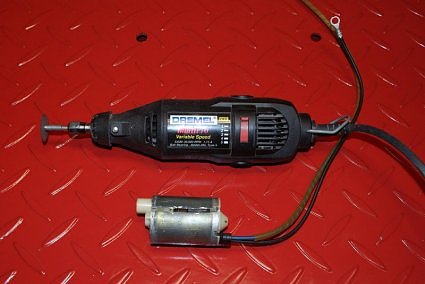
I pulled the pump out of it's housing by removing the white nylon clip at the end.
I used my trusty Dremel® tool to slice the case open. I also had to pry up the tabs that fold down over the end piece. Not a whole lot you can damage unless you go really deep with the Dremel®.
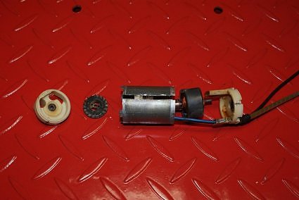
Here are the pieces starting to come out (this is after I semi cleaned everything up and put the pieces back in place for the photo).
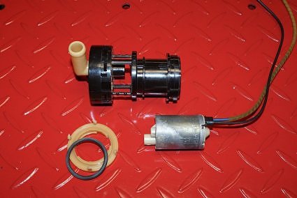
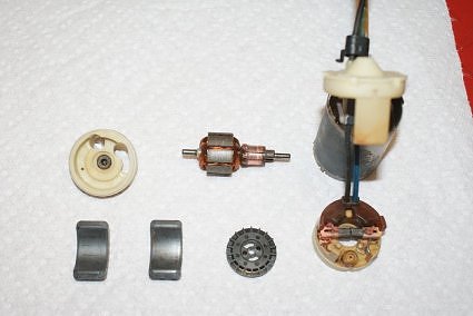
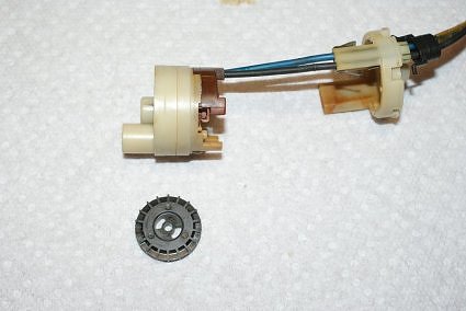
Here are all the parts cleaned and ready to go. The white circular piece (top left) is actually the front part of the pump chamber. The large hole with the slot is where fuel flows in an get pushed out the circular hole which has a little nozzle on it. Look at the brushes - this pump ran for 100,000 miles and there is still plenty of material left.
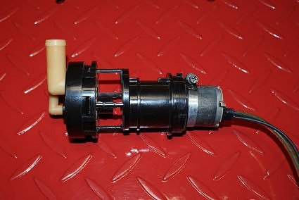
I put everything back and used that hose clamp to hold it together for now. I started sliding it back into the housing (it's actually a pretty tight fit) I just removed the hose clamp and slid it the rest of the way in. The slice in the casing didn't really seem to have any effect on the pump or it's performance.
Here is a better picture of the components with the armature and magnets removed. The black impeller goes inside the housing directly above it and the armature has two 'forks' that fit into the two slots of the impeller. The larger nozzle on the left is for 'fuel out'.
It is possible that the "guts" of the pump may slide out - but due to the wiring, I think it is going to have to all slide out in one direction. I really didn't expect to get the pump working again and the easiest way to take it apart was to cut it open. Actually, I don't think the cut really effects very much - the case may be just a hair bigger now but is contained by the housing. The armature rides in the synthetic end caps so it shouldn't be effected. I put a couple of thousand miles on it and ended up selling the bike.
~~~
Thank You again for your contribution John Hudson, aka GitSum, STOC #8086
~~~
Fuel Pump Repair ( ST1100 )
Here is how I was able to revive my OEM pump.
I originally took it apart to just see how it worked, but the only thing wrong with it that I could find was that it was
pretty well "crudded up"
First of all - this is what the armature and magnets looked like once I pulled it apart! Geez, I wonder why it stopped working!
I pulled the pump out of it's housing by removing the white nylon clip at the end.
I used my trusty Dremel® tool to slice the case open. I also had to pry up the tabs that fold down over the end piece. Not a whole lot you can damage unless you go really deep with the Dremel®.
Here are the pieces starting to come out (this is after I semi cleaned everything up and put the pieces back in place for the photo).
Here are all the parts cleaned and ready to go. The white circular piece (top left) is actually the front part of the pump chamber. The large hole with the slot is where fuel flows in an get pushed out the circular hole which has a little nozzle on it. Look at the brushes - this pump ran for 100,000 miles and there is still plenty of material left.
I put everything back and used that hose clamp to hold it together for now. I started sliding it back into the housing (it's actually a pretty tight fit) I just removed the hose clamp and slid it the rest of the way in. The slice in the casing didn't really seem to have any effect on the pump or it's performance.
Here is a better picture of the components with the armature and magnets removed. The black impeller goes inside the housing directly above it and the armature has two 'forks' that fit into the two slots of the impeller. The larger nozzle on the left is for 'fuel out'.
It is possible that the "guts" of the pump may slide out - but due to the wiring, I think it is going to have to all slide out in one direction. I really didn't expect to get the pump working again and the easiest way to take it apart was to cut it open. Actually, I don't think the cut really effects very much - the case may be just a hair bigger now but is contained by the housing. The armature rides in the synthetic end caps so it shouldn't be effected. I put a couple of thousand miles on it and ended up selling the bike.
~~~
Thank You again for your contribution John Hudson, aka GitSum, STOC #8086
#68
ST1300 Archive of Wisdom / Re: Rear Wheel Inner Fender Ex...
Last post by KoTAOW - March 27, 2012, 07:12:55 PMRear Wheel Inner Fender Extender ( ST1300 )
Comments by Chuck Henderson, STOC #086:
Here is one I made for the my ST1300.
More than welcome to copy it.
I use automotive trim buttons to attach it to the rear inner fender.
~~~
Thank you for your contribution Chuck Henderson, STOC #086
#69
ST1300 Archive of Wisdom / Rear Wheel Inner Fender Extend...
Last post by KoTAOW - March 27, 2012, 07:12:28 PMOriginal thread here: http://www.st-riders.net/index.php?topic=1481.0
Comments by John OoSTerhuis, STOC #1058:
As some of you may have noticed, I've reported riding a few gravel and dirt roads in the last year. And most recently just this week on some wet ones, not to mention a lot of wet and sandy pavement. The ST is pretty dirty of course, but I didn't realize just quite how dirty until I pulled the fuel tank yesterday to fix a coolant leak.
Sand, dirt, pebbles... all over the top of the swingarm and the exhaust collector. YIKES! And the stuff was 1" deep on top of my AudioVox CC vacuum canister which is slung below (mostly blocking) the gap between the swingarm front cross-members:
Sorry no pictures of the actual mess. I couldn't stand it and immediately cleaned it up. Can't have an SSMST that dirty, even on the inside. :)
So... would all you folks that have farkled those cool rear wheel inner fender extensions kindly poST your pictures and how-to/materials info for me...? Please? TIA
~~~
Comments by Carroll Walker, STOC #3176:
I didn't have the tank out of the bike so I could not get photos of the other side (front side) but I think this should give you some ideas. Not sure what material I use but it is some type of plastic I had on hand. Someone told me they had used a one gallon oil container to make a fender extender. I think most any type of plastic should work as there is very little movement in the extender after installation. I could have extended the left side just a little more, maybe on the second edition!!
~~~
Comments by Chuck Henderson, STOC #086:
My KLR just happens to be on the lift waiting for tires. So here is the extender i farkled on the KLR. should give you some ideas. Just a small piece of rubber mat zipped tied to the rear fender. Silver STorm will get this farkle next time the tires are replaced.
~~~
Comments by Paul Kolbo, STOC #273:
That looks similar to the vinyl piece I attached to the inner fender on my ST1100. I bought the vinyl from Home Depot (look in the flooring section). The ST1100 allows the extender to hang down in front of the swingarm. I used small stainless steel bolts and nuts to secure the piece. I also bonded the surfaces with RTV for good measure. Sorry, I have no pictures and the bike is currently stored in the corner of the cold garage.
~~~
Comments by Don da Roza, STOC #5230:
Just a thought, but might to want to consider using rivets instead of screws as they might be more secure for that application.
Reply by Carroll Walker, STOC #3176:
I thought of that but I wanted the option of removed the extension if necessary in case I had to remove the swing-arm. The hardware I used was stainless steel and therefore will not rust plus I applied just a small amount of 'Locktite' to the threads to prevent the hardware from becoming loose. In fact I had to remove the extension one time but I can't remember the reason, must be old age!!
~~~
Comments by Jason Spradlin, STOC #5043:
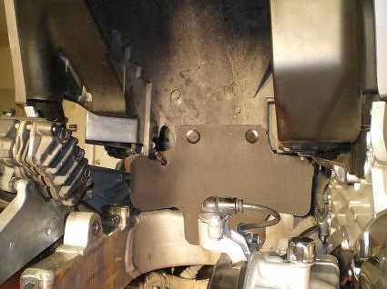
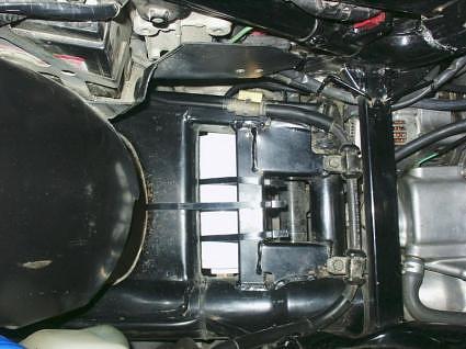
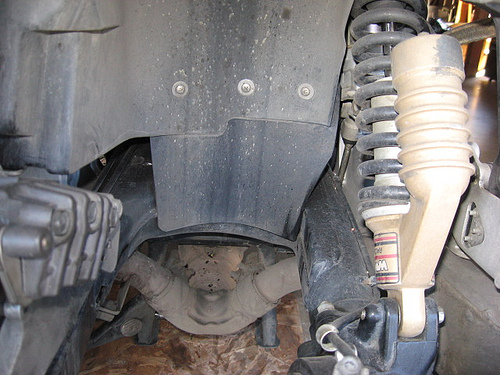
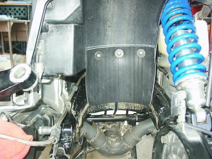
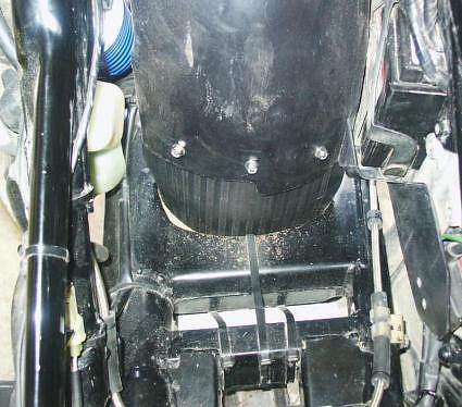
Before pic shows holes drilled for mudflap indicated by yellow arrows. Have to BE CAREFUL not to drill into the battery tray when locating the left hole. Before I cleaned the swingarm it looked like the exhaust.
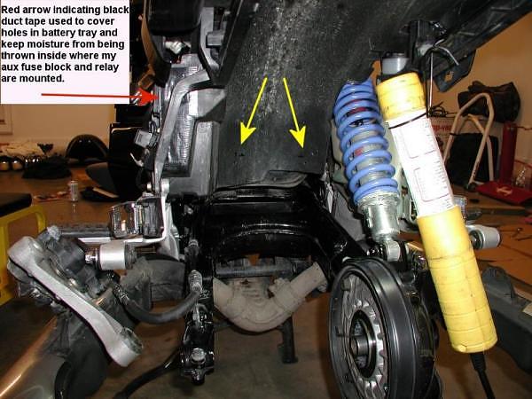
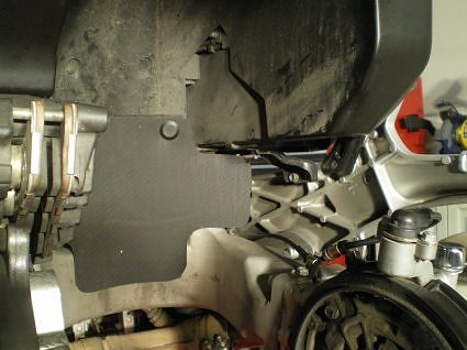
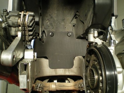
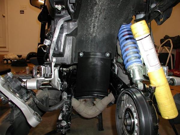
After photo shows mudflap installed. It should keep muck out of the swingarm pivot/engine/tranny area. Mudflap was made from a black anti-freeze jug. Simply cut out the entire front or rear area of the jug and trim to fit, then punch your two mounting holes. Mudflap could be made longer to cover exhaust but I was affraid it would melt from heat. Could maybe add thick rubber extension to the bottom for exhaust coverage.
I also made one for my FZ1 out of an actual truck mudflap from NAPA - next time the rear wheel is off the ST, I might remake one from this material for it. Pics here http://www.yamahafz1oa.com/forum/showthread.php?t=74763&highlight=mudflap
~~~
Additional comments by John OoSTerhuis, STOC #105:
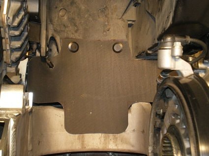
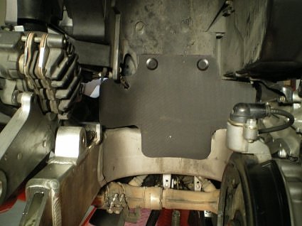
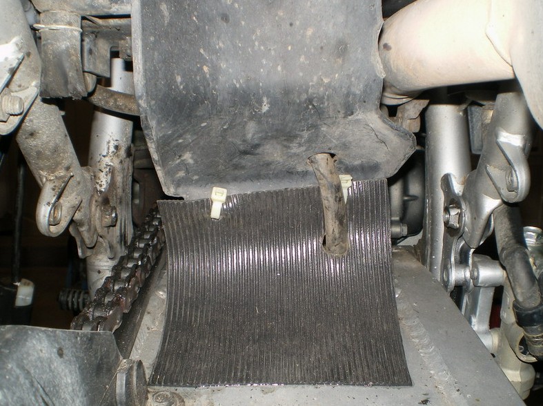
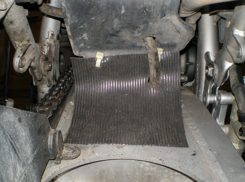
I finally got around to finishing my Galfer stainless steel rear brake line installation (will post separately about that). Before reinstalling the rear wheel and fuel tank I finished up the back end with an inner fender extension:
I'd purchased a heavy plastic mud flap from AutoZone but it proved too rigid to work with and get in the proper shape and contour. Then I found a stair tread at Home Depot that you see in the picture. I think it'll work out fine. I used stainless steel screws, washers, and nyloc nuts. Here's a picture of the other, fuel tank side:
Hopefully this fender extension will keep out all the dirt that'd been collecting on/in the swingarm.
BTW, there is a commercial version available from a UK outfit, Bike-Quip:
http://www.st1300-accessories.co.uk/st1100_shock_protect.html
~~~
Thank You all for your contributions.
Rear Wheel Inner Fender Extender ( ST1100 )
Comments by John OoSTerhuis, STOC #1058:
As some of you may have noticed, I've reported riding a few gravel and dirt roads in the last year. And most recently just this week on some wet ones, not to mention a lot of wet and sandy pavement. The ST is pretty dirty of course, but I didn't realize just quite how dirty until I pulled the fuel tank yesterday to fix a coolant leak.
Sand, dirt, pebbles... all over the top of the swingarm and the exhaust collector. YIKES! And the stuff was 1" deep on top of my AudioVox CC vacuum canister which is slung below (mostly blocking) the gap between the swingarm front cross-members:
Sorry no pictures of the actual mess. I couldn't stand it and immediately cleaned it up. Can't have an SSMST that dirty, even on the inside. :)
So... would all you folks that have farkled those cool rear wheel inner fender extensions kindly poST your pictures and how-to/materials info for me...? Please? TIA
~~~
Comments by Carroll Walker, STOC #3176:
I didn't have the tank out of the bike so I could not get photos of the other side (front side) but I think this should give you some ideas. Not sure what material I use but it is some type of plastic I had on hand. Someone told me they had used a one gallon oil container to make a fender extender. I think most any type of plastic should work as there is very little movement in the extender after installation. I could have extended the left side just a little more, maybe on the second edition!!
~~~
Comments by Chuck Henderson, STOC #086:
My KLR just happens to be on the lift waiting for tires. So here is the extender i farkled on the KLR. should give you some ideas. Just a small piece of rubber mat zipped tied to the rear fender. Silver STorm will get this farkle next time the tires are replaced.
~~~
Comments by Paul Kolbo, STOC #273:
That looks similar to the vinyl piece I attached to the inner fender on my ST1100. I bought the vinyl from Home Depot (look in the flooring section). The ST1100 allows the extender to hang down in front of the swingarm. I used small stainless steel bolts and nuts to secure the piece. I also bonded the surfaces with RTV for good measure. Sorry, I have no pictures and the bike is currently stored in the corner of the cold garage.
~~~
Comments by Don da Roza, STOC #5230:
Just a thought, but might to want to consider using rivets instead of screws as they might be more secure for that application.
Reply by Carroll Walker, STOC #3176:
I thought of that but I wanted the option of removed the extension if necessary in case I had to remove the swing-arm. The hardware I used was stainless steel and therefore will not rust plus I applied just a small amount of 'Locktite' to the threads to prevent the hardware from becoming loose. In fact I had to remove the extension one time but I can't remember the reason, must be old age!!
~~~
Comments by Jason Spradlin, STOC #5043:
Before pic shows holes drilled for mudflap indicated by yellow arrows. Have to BE CAREFUL not to drill into the battery tray when locating the left hole. Before I cleaned the swingarm it looked like the exhaust.
After photo shows mudflap installed. It should keep muck out of the swingarm pivot/engine/tranny area. Mudflap was made from a black anti-freeze jug. Simply cut out the entire front or rear area of the jug and trim to fit, then punch your two mounting holes. Mudflap could be made longer to cover exhaust but I was affraid it would melt from heat. Could maybe add thick rubber extension to the bottom for exhaust coverage.
I also made one for my FZ1 out of an actual truck mudflap from NAPA - next time the rear wheel is off the ST, I might remake one from this material for it. Pics here http://www.yamahafz1oa.com/forum/showthread.php?t=74763&highlight=mudflap
~~~
Additional comments by John OoSTerhuis, STOC #105:
I finally got around to finishing my Galfer stainless steel rear brake line installation (will post separately about that). Before reinstalling the rear wheel and fuel tank I finished up the back end with an inner fender extension:
I'd purchased a heavy plastic mud flap from AutoZone but it proved too rigid to work with and get in the proper shape and contour. Then I found a stair tread at Home Depot that you see in the picture. I think it'll work out fine. I used stainless steel screws, washers, and nyloc nuts. Here's a picture of the other, fuel tank side:
Hopefully this fender extension will keep out all the dirt that'd been collecting on/in the swingarm.
BTW, there is a commercial version available from a UK outfit, Bike-Quip:
http://www.st1300-accessories.co.uk/st1100_shock_protect.html
~~~
Thank You all for your contributions.
#70
ST1100 Archive of Wisdom / Re: Rear Wheel Inner Fender Ex...
Last post by KoTAOW - March 27, 2012, 04:51:55 PMRear Wheel Inner Fender Extender ( ST1300 )
Comments by Chuck Henderson, STOC #086:
Here is one I made for the my ST1300.
More than welcome to copy it.
I use automotive trim buttons to attach it to the rear inner fender.
~~~
Thank you for your contribution Chuck Henderson, STOC #086