- Welcome to ST-Riders - The liST.

The Original ST1100/ST1300 Forum
Recent posts
#91
ST1100 Archive of Wisdom / Re: ABS 1 - Modulator Assembly...
Last post by KoTAOW - February 17, 2012, 09:34:13 PMOriginal article can be found here: http://www.my-mc.com/messages/1/120551.html?1254805607
Comments by Mike Fisher, STOC #2490:
First the resistance readings:
Front defective modulator:
Motor - 0.8 Ohms
Solenoids - from earth to input Pin 1 - 2.6 Ohms
from earth to input Pin 2 - 2.6 Ohms
from input pin 1 to input pin 2 - 5.0 Ohms
Rear working modulator:
Motor - 1.2 Ohms
Solenoids - from earth to input Pin 1 - 2.6 Ohms
from earth to input Pin 2 - 2.6 Ohms
from input pin 1 to input pin 2 - 5.0 Ohms
As you can see they look very similar and from listening, electrically the faulty modulator appears to function correctly.
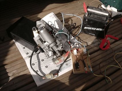
Before I started the strip, I thought I'd just eliminate the controller just for peace of mind. So by using linking wires I disconnected all the plugs and linked the rear modulator to the front modulators plugs and vice versa. The result was as expected I got a code 2 on the ABS diagnostic which is failure in the rear hydraulic system instead of the code 1 failure in the front hydraulic system, this proved the rear modulator passed it's tests and the front failed.
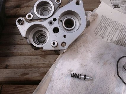
I should be stripping the modulator in a dust/dirt free Nissan laboratory, but as I've no workshop some newspaper on the decking in the garden will have to do!
This photo shows the limit switch with the diaphragm below it.
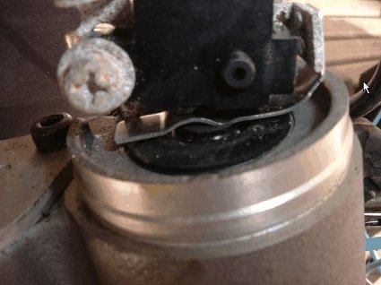
The rear modulator with the ignition off and the pump running will develop pressure and you can see it push the limit switch, I agree with Norm, I think these modulators are sealed and I think a working modulator on the bench with the pump spinning will activate the switch, but the only definite way to prove this would be to remove my rear modulator but time does not allow this (unless someone has one lying around they could try).
This photo shows some tests I did before stripping it, I tried actuating the solenoids in all combinations I could think of but the modulator failed to push the limit switch, I also tried removing the limit switch and feeling the diaphragm with my finger while the pump was running but I couldn't feel any pressure what so ever.
This photo shows the limit switch removed with the plate next to it which is what I mentioned in a previous thread is similar to the brake master cylinder and appears to be a reservoir of brake fluid.

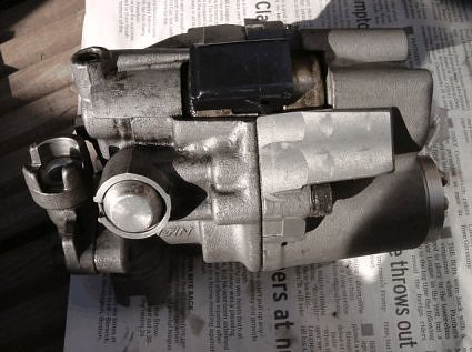
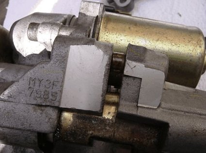
This photos shows where the modulator splits, the cut-off valve is separate and is on the left where the brake line attaches.
This photo shows the cut-off valve.
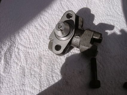
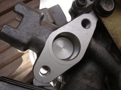
This photo shows where the cut-off valve attaches and you can see the expander piston. It will not move with finger pressure (with the brake fluid drained).
This photo shows the splitting of the modulator into it's two halves, this is not too difficult as long as you are careful. The difficult bit is a dowel seen in the photo as dark brown (with corrosion) which was tight.
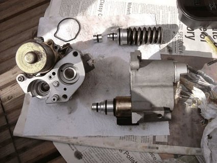
This photo shows the major components. The backup piston is the unit with the large spring (no wonder I couldn't press the expander piston with my finger). Next to it is the expander piston from the workshop manual I thought this was attached to the cut-off valve, well as can be seen this is not the case.
At the bottom of the picture still in the top half of the modulator housing is the enclosed unit containing the solenoids.
On the left is the bottom half of the modulator housing which the pump still attached, in the middle of this housing just below the white plastic hole is a smaller piston with a spring behind it, which I thought seemed stuck down, a few pushes and it freed and moved in and out OK.
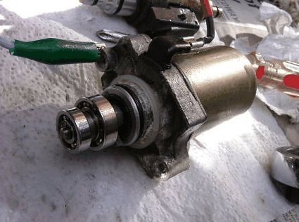
This photo shows the pump, it works a treat.
This photo shows the small piston I thought was stuck.
I'm sorry I can't provide a more in depth postmortem.
I checked and could not find anything obvious, everything looked in really good condition, I didn't have time to workout exactly how it all worked (sorry Norm) my objective was to strip it and try and find an obviously failed component, give it a good clean and reassemble and test.
In the tech manual it shows some non-return valves, which are shown as ball bearings similar to a BSA I have. These were not obvious and I was rushing at this stage. I quickly reassembled it carefully filling each part with brake fluid as I went and when it was tested unfortunately it was still in the same state.
This was not as professional an investigation as I would have liked to present to you but I will have another look with a bit more care when I get another opportunity.
Conclusion:
1) Possibly a non-return valve I overlooked.
2) Possibly it needs re-filling in a certain order to allow it to build up pressure.
3) Possibly it needs connecting to the brake system to function (I don't think this is the case).
Also, I purchased a modulator over the internet as a sold as seen a couple of years ago when my rear failed (which turned out to be the limit switch needing adjustment). This modulator turned out to be from a ABSII bike, this should be a working model. Hopefully this will allow the opportunity for both ABS systems to then be documented by someone competent, I think at present the ABS on the ST1100 is the only area that is still unserviceable.
~~~
Thank You for your contribution, Mike Fisher, STOC #2490.
ABS 1 - Modulator Assembly Tutorial ( ST1100 ) - Part #4
Comments by Mike Fisher, STOC #2490:
First the resistance readings:
Front defective modulator:
Motor - 0.8 Ohms
Solenoids - from earth to input Pin 1 - 2.6 Ohms
from earth to input Pin 2 - 2.6 Ohms
from input pin 1 to input pin 2 - 5.0 Ohms
Rear working modulator:
Motor - 1.2 Ohms
Solenoids - from earth to input Pin 1 - 2.6 Ohms
from earth to input Pin 2 - 2.6 Ohms
from input pin 1 to input pin 2 - 5.0 Ohms
As you can see they look very similar and from listening, electrically the faulty modulator appears to function correctly.
Before I started the strip, I thought I'd just eliminate the controller just for peace of mind. So by using linking wires I disconnected all the plugs and linked the rear modulator to the front modulators plugs and vice versa. The result was as expected I got a code 2 on the ABS diagnostic which is failure in the rear hydraulic system instead of the code 1 failure in the front hydraulic system, this proved the rear modulator passed it's tests and the front failed.
I should be stripping the modulator in a dust/dirt free Nissan laboratory, but as I've no workshop some newspaper on the decking in the garden will have to do!
This photo shows the limit switch with the diaphragm below it.
The rear modulator with the ignition off and the pump running will develop pressure and you can see it push the limit switch, I agree with Norm, I think these modulators are sealed and I think a working modulator on the bench with the pump spinning will activate the switch, but the only definite way to prove this would be to remove my rear modulator but time does not allow this (unless someone has one lying around they could try).
This photo shows some tests I did before stripping it, I tried actuating the solenoids in all combinations I could think of but the modulator failed to push the limit switch, I also tried removing the limit switch and feeling the diaphragm with my finger while the pump was running but I couldn't feel any pressure what so ever.
This photo shows the limit switch removed with the plate next to it which is what I mentioned in a previous thread is similar to the brake master cylinder and appears to be a reservoir of brake fluid.
This photos shows where the modulator splits, the cut-off valve is separate and is on the left where the brake line attaches.
This photo shows the cut-off valve.
This photo shows where the cut-off valve attaches and you can see the expander piston. It will not move with finger pressure (with the brake fluid drained).
This photo shows the splitting of the modulator into it's two halves, this is not too difficult as long as you are careful. The difficult bit is a dowel seen in the photo as dark brown (with corrosion) which was tight.
This photo shows the major components. The backup piston is the unit with the large spring (no wonder I couldn't press the expander piston with my finger). Next to it is the expander piston from the workshop manual I thought this was attached to the cut-off valve, well as can be seen this is not the case.
At the bottom of the picture still in the top half of the modulator housing is the enclosed unit containing the solenoids.
On the left is the bottom half of the modulator housing which the pump still attached, in the middle of this housing just below the white plastic hole is a smaller piston with a spring behind it, which I thought seemed stuck down, a few pushes and it freed and moved in and out OK.
This photo shows the pump, it works a treat.
This photo shows the small piston I thought was stuck.
I'm sorry I can't provide a more in depth postmortem.
I checked and could not find anything obvious, everything looked in really good condition, I didn't have time to workout exactly how it all worked (sorry Norm) my objective was to strip it and try and find an obviously failed component, give it a good clean and reassemble and test.
In the tech manual it shows some non-return valves, which are shown as ball bearings similar to a BSA I have. These were not obvious and I was rushing at this stage. I quickly reassembled it carefully filling each part with brake fluid as I went and when it was tested unfortunately it was still in the same state.
This was not as professional an investigation as I would have liked to present to you but I will have another look with a bit more care when I get another opportunity.
Conclusion:
1) Possibly a non-return valve I overlooked.
2) Possibly it needs re-filling in a certain order to allow it to build up pressure.
3) Possibly it needs connecting to the brake system to function (I don't think this is the case).
Also, I purchased a modulator over the internet as a sold as seen a couple of years ago when my rear failed (which turned out to be the limit switch needing adjustment). This modulator turned out to be from a ABSII bike, this should be a working model. Hopefully this will allow the opportunity for both ABS systems to then be documented by someone competent, I think at present the ABS on the ST1100 is the only area that is still unserviceable.
~~~
Thank You for your contribution, Mike Fisher, STOC #2490.
#92
ST1100 Archive of Wisdom / Re: ABS 1 - Modulator Assembly...
Last post by KoTAOW - February 17, 2012, 09:33:13 PMOriginal thread and post can be found here: http://www.my-mc.com/messages/1/120551.html?1254805607
Initial comments by Mike Fisher, STOC #2490:
I'm after some advice, but first I'll share what experience I've had on the ABS system which may be of help to someone (this is the early ABS system up to 1995).
All the problems I've had are to do with the modulator, there are a number of parts to it that will cause a failure if they malfunction. These are the solenoids, the pump and the limit switch. You can check all of these for basic functionality ie check they're not seized.
1) Solenoids: There are two solenoids and they are controlled by a voltage applied via the three pin connector on the side of the modulator. To check they are not seized remove the three pin plug and on the three pins on the modulator put an earth on the center pin (this is from memory so check wiring diagrams first) and briefly touch 12V on each of the outer two pins, you should hear a click as the solenoid moves if 12V on both outer pins produces a click then the two solenoids are OK. Be careful not to short across the pins as access is difficult as the connector is deep and narrow
2) Pump: This is controlled by a voltage to the single connector on the side of the modulator. To check this (ensure the modulator is earthed) remove the plug on the connector and briefly apply 12v to the connector and you should hear the motor spin.
3) Limit switch: This is what the wires running from the plastic cover on the top of the modulator connect to, the wires run to a two pin connector near the modulator. This can be checked by unplugging the two pin connector and putting a meter on the two pins to measure the resistance across the switch. You should have an open circuit, now you need to spin the pump either by touching 12V on the single pump connector for approx 3-5 sec or with all the other connectors in place start the engine and let it go through it's self checks. You should see a closed circuit on the switches resistance. If you don't, then you either have a problem with a faulty switch or pressure in the modulator. To check these you need to pry off the plastic cover on top of the modulator (be careful here as it's very tight). With it off you will see the limit switch sitting over a rubber diaphragm with a metal center, when the pump spins it builds up pressure and pushes up the diaphragm which connects with the switch and closes it (you can see this happening). To check the switch you can move it by hand and see with a meter if it's OK. This switch is also adjustable. I had a modulator fail and carried out the above checks and could see the diaphragm moving but it wasn't activating the switch, i adjusted the switch down very sightly so the diaphragm would activate it and it's been OK for a couple of years now.
Now the advice if anyone can help, I've just had my front modulator fail and the problem I've found is that when the pump spins it doesn't push up the diaphragm so it's not building up pressure (everything else appears OK). I'm wondering if it's got air in the modulator, it seems to be a sealed unit, anyone got any ideas or had experience with this type of issue.
~~~
Comments by Norm Keller, STOC #8030:
Before discarding a pump which will operate but produces low pressure, I would remove the pump and connect a temporary inlet and outlet hose. Use the hoses to flush the pump with ISO-alcohol and warm soapy water (followed by alcohol and brake fluid to remove water residue). Alcohol and warm soapy water will often dissolve brake fluid residue.
It would be ideal to get may hands on some of these failed components for study and possible repair.
Others have frequently made the point that the brake & clutch hydraulic fluid should be changed each year to remove contaminants such as water. The small copper crystals found in brake lines (tubing) act as corrosion points when any water is present.
~~~
Reply by Mike Fisher, STOC #2490:
These ABS modulators are frustrating because of the lack of service information, the information you get is "if it fails replace it".
The problem I have is my lack of knowledge on what goes on in these systems, i can see there is the two solenoids somehow controlling how the fluid goes in and out and a pump building pressure that is controlled by the limit switch but that's as far as it goes.
Norm you suggest flushing the modulator, however I always had the idea they were a sealed isolated unit that the brake fluid bypassed them when they were not activated, if I'm right and I remove them and try to flush them then the fluid is just gonna go into and out of the modulator bypassing the internal workings, in the Honda tech manual it says you can't bleed them as they are sealed (seems a bit stupid).
I would hazard a guess I would have to have one of the solenoids activated or something like that.
I've attached some info I've found in the tech manual on how they operate with some diagrams, if you've a bit of spare time I would be very interested (and grateful) if you could have a look and give your opinion on how you would go about tackling this issue with the tech info provided, maybe there is a sequence that could be worked out.
~~~
Thank You for your contribution, Norm Keller, STOC #8030 and Mike Fisher, STOC #2490.
ABS 1 - Modulator Assembly Tutorial ( ST1100 ) - Part #3
Initial comments by Mike Fisher, STOC #2490:
I'm after some advice, but first I'll share what experience I've had on the ABS system which may be of help to someone (this is the early ABS system up to 1995).
All the problems I've had are to do with the modulator, there are a number of parts to it that will cause a failure if they malfunction. These are the solenoids, the pump and the limit switch. You can check all of these for basic functionality ie check they're not seized.
1) Solenoids: There are two solenoids and they are controlled by a voltage applied via the three pin connector on the side of the modulator. To check they are not seized remove the three pin plug and on the three pins on the modulator put an earth on the center pin (this is from memory so check wiring diagrams first) and briefly touch 12V on each of the outer two pins, you should hear a click as the solenoid moves if 12V on both outer pins produces a click then the two solenoids are OK. Be careful not to short across the pins as access is difficult as the connector is deep and narrow
2) Pump: This is controlled by a voltage to the single connector on the side of the modulator. To check this (ensure the modulator is earthed) remove the plug on the connector and briefly apply 12v to the connector and you should hear the motor spin.
3) Limit switch: This is what the wires running from the plastic cover on the top of the modulator connect to, the wires run to a two pin connector near the modulator. This can be checked by unplugging the two pin connector and putting a meter on the two pins to measure the resistance across the switch. You should have an open circuit, now you need to spin the pump either by touching 12V on the single pump connector for approx 3-5 sec or with all the other connectors in place start the engine and let it go through it's self checks. You should see a closed circuit on the switches resistance. If you don't, then you either have a problem with a faulty switch or pressure in the modulator. To check these you need to pry off the plastic cover on top of the modulator (be careful here as it's very tight). With it off you will see the limit switch sitting over a rubber diaphragm with a metal center, when the pump spins it builds up pressure and pushes up the diaphragm which connects with the switch and closes it (you can see this happening). To check the switch you can move it by hand and see with a meter if it's OK. This switch is also adjustable. I had a modulator fail and carried out the above checks and could see the diaphragm moving but it wasn't activating the switch, i adjusted the switch down very sightly so the diaphragm would activate it and it's been OK for a couple of years now.
Now the advice if anyone can help, I've just had my front modulator fail and the problem I've found is that when the pump spins it doesn't push up the diaphragm so it's not building up pressure (everything else appears OK). I'm wondering if it's got air in the modulator, it seems to be a sealed unit, anyone got any ideas or had experience with this type of issue.
~~~
Comments by Norm Keller, STOC #8030:
Before discarding a pump which will operate but produces low pressure, I would remove the pump and connect a temporary inlet and outlet hose. Use the hoses to flush the pump with ISO-alcohol and warm soapy water (followed by alcohol and brake fluid to remove water residue). Alcohol and warm soapy water will often dissolve brake fluid residue.
It would be ideal to get may hands on some of these failed components for study and possible repair.
Others have frequently made the point that the brake & clutch hydraulic fluid should be changed each year to remove contaminants such as water. The small copper crystals found in brake lines (tubing) act as corrosion points when any water is present.
~~~
Reply by Mike Fisher, STOC #2490:
These ABS modulators are frustrating because of the lack of service information, the information you get is "if it fails replace it".
The problem I have is my lack of knowledge on what goes on in these systems, i can see there is the two solenoids somehow controlling how the fluid goes in and out and a pump building pressure that is controlled by the limit switch but that's as far as it goes.
Norm you suggest flushing the modulator, however I always had the idea they were a sealed isolated unit that the brake fluid bypassed them when they were not activated, if I'm right and I remove them and try to flush them then the fluid is just gonna go into and out of the modulator bypassing the internal workings, in the Honda tech manual it says you can't bleed them as they are sealed (seems a bit stupid).
I would hazard a guess I would have to have one of the solenoids activated or something like that.
I've attached some info I've found in the tech manual on how they operate with some diagrams, if you've a bit of spare time I would be very interested (and grateful) if you could have a look and give your opinion on how you would go about tackling this issue with the tech info provided, maybe there is a sequence that could be worked out.
~~~
Thank You for your contribution, Norm Keller, STOC #8030 and Mike Fisher, STOC #2490.
#93
ST1100 Archive of Wisdom / Re: ABS 1 - Modulator Assembly...
Last post by KoTAOW - February 17, 2012, 09:32:41 PMABS 1 - Modulator Assembly Tutorial ( ST1100 ) - Part #2
Note: ABS 1 - Modulator Assembly used on 1992-1995 ST1100A
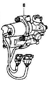
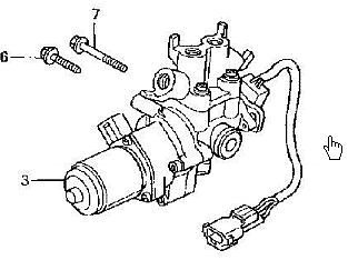
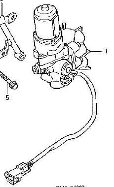
ABS 1 - Front Modulator Assembly ( 57600-MY3-782 )
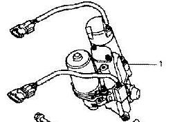
ABS 1 - Rear Modulator Assembly ( 57100-MY3-782 )
Approximate 2012 prices ( New ): $1,370.00
Honda Service Manual, Chapter 16A, 1992-1995
~~~
Note: ABS 2 - Modulator Assembly used on 1996-2002 ST1100A
ABS 2 - Front Modulator Assembly ( 57600-MAJ-G41 )
ABS 2 - Rear Modulator Assembly ( 57100-MAJ-G41 )
Approximate 2012 prices ( New ): Front = $1,200.00 and Rear = $650.00
Honda Service Manual, Chapter 16A, 1996-2002
#94
ST1100 Archive of Wisdom / ABS 1 - Modulator Assembly Tut...
Last post by KoTAOW - February 17, 2012, 09:32:10 PMABS 1 - Modulator Assembly Tutorial ( ST1100 ) - Part #1
Following comments by KotAOW:
Disclaimer:
The information contained in this article is for general information only. Whilst the author(s) endeavors to ensure the accuracy of this general information, no statement, representation, warranty or guarantee, express or implied, is given as to its accuracy or appropriateness for use in any particular circumstances.
The author(s) are not responsible for any loss or damage whatsoever arising out of or in connection with any information on this specific subject. Users are responsible for making their own assessment of all information contained in this article and are advised to verify such information.
~~~
Purpose:
This article is a collection of many threads posted on several different forums over the past years. It is NOT to be considered a "how-to or step-by-step" procedure for repairing the ABS 1 system on early ST1100's. There is a wealth of knowledge in these articles and each reader must decide whether it is in their individual expertise before attempting any repairs to a braking system on a motorcycle, especially an ABS system.
Hopefully by carefully reading thru each section, the reader will absorb enough of the theory and understanding of a very complex part of the ST1100 motorcycle, before making a decision on whether to proceed or not.
The ABS Modulators are very expensive to replace and very difficult to troubleshoot down to the component level. If after reading thru this information, you feel it is within your expertise, then by all means, proceed and GOOD LUCK.
Also, please post to this forum any successes and failures that you may have occurred in regards to the ABS repair and service.
~~~
#95
ST1300 Archive of Wisdom / Shorai Lithium Iron Battery ( ...
Last post by KoTAOW - February 13, 2012, 04:32:29 PMInformation and Comments by Tim Shevlin, STOC #1183 and Steve Kelley, STOC #077
Related installation thread with photo's on a 2009 R1200R, BMW: http://www.advrider.com/forums/showthread.php?t=650857
~~~
Links:
Shorai Lithium Batteries Shorai Battery Chargers
Shorai Battery - ST1100 Shorai Battery - ST1300
~~~
Comments by Tim Shevlin: If you're willing to gamble on really new technology, consider replacing your tired battery with a new Shorai. I have been using my new Shorai for a whole month now (!!) and it's still working as advertised. (it is a remarkable product, IMHO) And getting a little weight off of the right side of the ST1300 doesn't hurt either.
Just got an e-notice from Chaparral that features a special on Shorai batteries for less than I paid. (grrrr...) Go for it.
~~~
Comments by Steve Kelly:
Here is the info on what I ordered:
Battery Info
SKU:4897034420111
Product:LFX18A1-BS12
Price: $189.95
Charger Info
SKU: 4897034420289
Product: SHO-BMS01
Price: $79.95
SubTotal: $269.90
Shipping: FedEx Home Delivery $12.03
Tax: $0.00
Total: $281.93
~~~
Be sure to read their FAQ - for instance, you DO NOT want to use an anti-sulfating battery tender.
And I found the following fascinating as well as counter-intuitive:
Question: I hear that lithium crank poorly when it gets cold, is that right?
Answer: Lithium do increase in resistance more as temperature drops, compared to lead-acid. However, they also react to cranking under cold conditions in a much better way. Lead-acid will increase resistance on each subsequent cranking attempt, until it won’t turn over. If your LFX fails to start the engine on first crank, that first crank has warmed the battery, and the second attempt will be much stronger, and so on until you get a good start.
Shorai LFX are much better in cold-weather conditions than other-brand lithium starter batteries, due to our extreme-rate formulation with low resistance. Down to about 20 degrees Fahrenheit (-7C) most users find that they can start normally on first crank. If your headlight comes on at key-ON, it is good for the batteries to flow some current before cranking in cold weather. The suggested headlight-on time before cranking depends on the temperature. If starting at 40f (5C), 30 seconds will help wake the battery and increase cranking performance. If at 0f (-17C), leave the lights on for 4~5 minutes before cranking. The result will be a better first crank, and longer battery life. Any other accessories that can be turned on before cranking can also be used for this purpose, such as heated gear, radio, etc...
It is worth noting that, while the Shorai is 80% lighter than stock, acid free, and can be mounted in any position, it is also about 1/3 the size of a stock battery and must be shimmed into place. I popped for one and a charger direct from Shorai at retail. Not a good deal, but it's for my ST, and I don't have any other children.
~~~
Comments by Dauntless, from ADVRider forum:
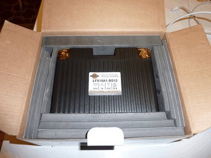
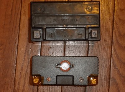
Here is what it looks like packed in the foam pieces that you must trim to make it match your original battery:
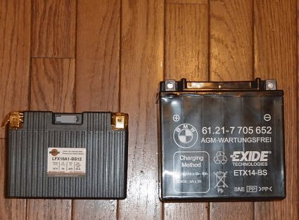
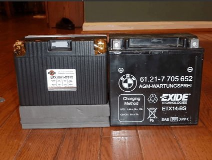
Here it is compared to my 2009 R1200R's original battery:
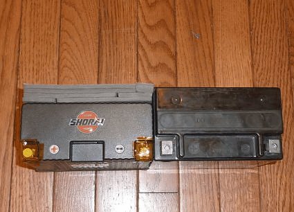
Here it is with the foam cut to shim the battery:
The battery is 7 pounds lighter than the original. It is so light that it makes you wonder how it can generate any power.
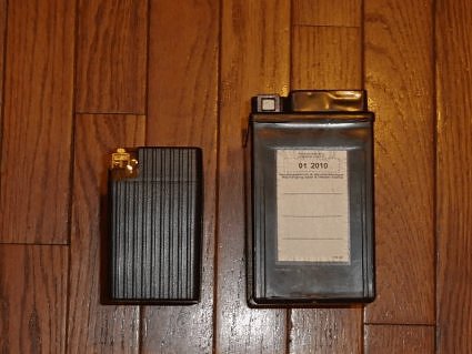
The battery was a PITA to install because the nut to which the terminal screw attaches falls away and out of reach if you have an accessory wire attached to the battery in addition to the main cable. I had to stick a piece of the foam under the nut in order to keep it in place and within reach of the screw. Here is a comparison of my original battery's pretty robust terminal and the Shorai's terminal:
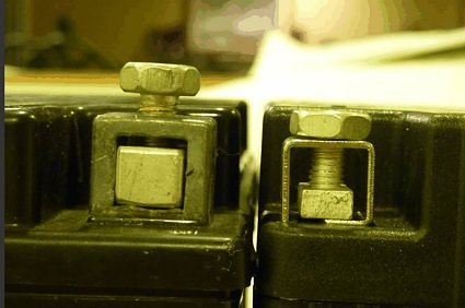
It would be nice if the nut was taller and the terminal itself was flush with the top of the battery. The way it is now, the leads of my battery cables are angled down to meet the terminal and probably don't have as good of a contact area as it would if the terminal was flush.
Further, the foam pads that shim the battery are exposed to water spray. I don't know how they will hold up or if they will retain water like a sponge.
If I had known that I had to cut foam to make this battery fit and shim the terminal nuts to make them work, I wouldn't have bought this battery. The weight savings isn't that important to me. I think an Odyssey battery would have served my purposes just fine.
Here is a good explanation of the benefits: http://www.novaelectric.com/life.php
Some advantages of the Lithium Ion Phosphate batteries are listed below for reference:
4X higher energy density than lead-acid battery: The gravimetric energy density of the LiFePO4 battery is ~130 Wh/kg, almost four times higher than that of a typical Lead-acid battery, at 35Wh/kg. For the UPS user, this means far greater run times while running on battery, without any space penalty.
Light Weight: Despite the vastly higher energy density, the LiFePO4 battery packs are, in most cases, only 1/3 the weight of conventional lead acid packs. So for applications where weight savings are critical, the use of LiFePO4 batteries can result in significant reductions in overall system weight.
Long Life: LiFePO4 battery packs typically achieve a minimum of 2000 cycles with 70% capacity remaining, with up to 5000 cycle potential. This is equivalent to the 8-12 year expected life the very best sealed, lead acid batteries offer. Further, LiFePO4 batteries do not suffer from the “memory effect†of some conventional lead acid batteries.
Better Voltage Regulation: Unlike the Lead acid battery, the LiFePO4 battery terminal voltage remains relatively constant during high rate discharge. This equates to much better performance during high rate (short time period) discharges, yielding a much better AH performance during this type of application, typical in UPS systems.
Wide Temp Range: LiFePO4 battery packs are typically sold for operation between -20°C to +60°C, charging between -10°C to +60°C, and storage between -40°C to +70°C. This is equivalent to the ranges that only premium sealed, lead acid batteries offer.
Safety with power: Safety is equivalent to or better than the traditional lead acid type, without the risk of explosion or fire outbreak associated with some other new battery technologies. The LiFePO4 battery has hybrid characteristics: it is as safe as the lead-acid battery and as powerful as the lithium ion battery.
A Greener Battery: The eco-friendly LiFePO4 battery packs are recyclable and non-toxic.
Battery Management: All LiFePO4 Batteries are provided with a Battery Management System (BMS) which protects the battery cells within the Nova LiFePO4 Battery pack. The BMS will protect the cells to be sure they do not go outside of the normal limits of Cell voltage of the minimum discharge voltage of 2.8 V, the working voltage of 3.0 V â€" 3.3 V, and the maximum charge voltage of 3.6 V. The BMS also provides short circuit protection which prevents high current in the event of an external short circuit.
~~~
Thank You again to everyone who contributed.
Related installation thread with photo's on a 2009 R1200R, BMW: http://www.advrider.com/forums/showthread.php?t=650857
~~~
Shorai Lithium Iron Battery ( ST1100\ST1300 )
Links:
Shorai Lithium Batteries Shorai Battery Chargers
Shorai Battery - ST1100 Shorai Battery - ST1300
~~~
Comments by Tim Shevlin: If you're willing to gamble on really new technology, consider replacing your tired battery with a new Shorai. I have been using my new Shorai for a whole month now (!!) and it's still working as advertised. (it is a remarkable product, IMHO) And getting a little weight off of the right side of the ST1300 doesn't hurt either.
Just got an e-notice from Chaparral that features a special on Shorai batteries for less than I paid. (grrrr...) Go for it.
~~~
Comments by Steve Kelly:
Here is the info on what I ordered:
Battery Info
SKU:4897034420111
Product:LFX18A1-BS12
Price: $189.95
Charger Info
SKU: 4897034420289
Product: SHO-BMS01
Price: $79.95
SubTotal: $269.90
Shipping: FedEx Home Delivery $12.03
Tax: $0.00
Total: $281.93
~~~
Be sure to read their FAQ - for instance, you DO NOT want to use an anti-sulfating battery tender.
And I found the following fascinating as well as counter-intuitive:
Question: I hear that lithium crank poorly when it gets cold, is that right?
Answer: Lithium do increase in resistance more as temperature drops, compared to lead-acid. However, they also react to cranking under cold conditions in a much better way. Lead-acid will increase resistance on each subsequent cranking attempt, until it won’t turn over. If your LFX fails to start the engine on first crank, that first crank has warmed the battery, and the second attempt will be much stronger, and so on until you get a good start.
Shorai LFX are much better in cold-weather conditions than other-brand lithium starter batteries, due to our extreme-rate formulation with low resistance. Down to about 20 degrees Fahrenheit (-7C) most users find that they can start normally on first crank. If your headlight comes on at key-ON, it is good for the batteries to flow some current before cranking in cold weather. The suggested headlight-on time before cranking depends on the temperature. If starting at 40f (5C), 30 seconds will help wake the battery and increase cranking performance. If at 0f (-17C), leave the lights on for 4~5 minutes before cranking. The result will be a better first crank, and longer battery life. Any other accessories that can be turned on before cranking can also be used for this purpose, such as heated gear, radio, etc...
It is worth noting that, while the Shorai is 80% lighter than stock, acid free, and can be mounted in any position, it is also about 1/3 the size of a stock battery and must be shimmed into place. I popped for one and a charger direct from Shorai at retail. Not a good deal, but it's for my ST, and I don't have any other children.
~~~
Comments by Dauntless, from ADVRider forum:
Here is what it looks like packed in the foam pieces that you must trim to make it match your original battery:
Here it is compared to my 2009 R1200R's original battery:
Here it is with the foam cut to shim the battery:
The battery is 7 pounds lighter than the original. It is so light that it makes you wonder how it can generate any power.
The battery was a PITA to install because the nut to which the terminal screw attaches falls away and out of reach if you have an accessory wire attached to the battery in addition to the main cable. I had to stick a piece of the foam under the nut in order to keep it in place and within reach of the screw. Here is a comparison of my original battery's pretty robust terminal and the Shorai's terminal:
It would be nice if the nut was taller and the terminal itself was flush with the top of the battery. The way it is now, the leads of my battery cables are angled down to meet the terminal and probably don't have as good of a contact area as it would if the terminal was flush.
Further, the foam pads that shim the battery are exposed to water spray. I don't know how they will hold up or if they will retain water like a sponge.
If I had known that I had to cut foam to make this battery fit and shim the terminal nuts to make them work, I wouldn't have bought this battery. The weight savings isn't that important to me. I think an Odyssey battery would have served my purposes just fine.
Here is a good explanation of the benefits: http://www.novaelectric.com/life.php
Some advantages of the Lithium Ion Phosphate batteries are listed below for reference:
4X higher energy density than lead-acid battery: The gravimetric energy density of the LiFePO4 battery is ~130 Wh/kg, almost four times higher than that of a typical Lead-acid battery, at 35Wh/kg. For the UPS user, this means far greater run times while running on battery, without any space penalty.
Light Weight: Despite the vastly higher energy density, the LiFePO4 battery packs are, in most cases, only 1/3 the weight of conventional lead acid packs. So for applications where weight savings are critical, the use of LiFePO4 batteries can result in significant reductions in overall system weight.
Long Life: LiFePO4 battery packs typically achieve a minimum of 2000 cycles with 70% capacity remaining, with up to 5000 cycle potential. This is equivalent to the 8-12 year expected life the very best sealed, lead acid batteries offer. Further, LiFePO4 batteries do not suffer from the “memory effect†of some conventional lead acid batteries.
Better Voltage Regulation: Unlike the Lead acid battery, the LiFePO4 battery terminal voltage remains relatively constant during high rate discharge. This equates to much better performance during high rate (short time period) discharges, yielding a much better AH performance during this type of application, typical in UPS systems.
Wide Temp Range: LiFePO4 battery packs are typically sold for operation between -20°C to +60°C, charging between -10°C to +60°C, and storage between -40°C to +70°C. This is equivalent to the ranges that only premium sealed, lead acid batteries offer.
Safety with power: Safety is equivalent to or better than the traditional lead acid type, without the risk of explosion or fire outbreak associated with some other new battery technologies. The LiFePO4 battery has hybrid characteristics: it is as safe as the lead-acid battery and as powerful as the lithium ion battery.
A Greener Battery: The eco-friendly LiFePO4 battery packs are recyclable and non-toxic.
Battery Management: All LiFePO4 Batteries are provided with a Battery Management System (BMS) which protects the battery cells within the Nova LiFePO4 Battery pack. The BMS will protect the cells to be sure they do not go outside of the normal limits of Cell voltage of the minimum discharge voltage of 2.8 V, the working voltage of 3.0 V â€" 3.3 V, and the maximum charge voltage of 3.6 V. The BMS also provides short circuit protection which prevents high current in the event of an external short circuit.
~~~
Thank You again to everyone who contributed.
#96
ST1100 Archive of Wisdom / Re: Driveshaft and U-Joint Rep...
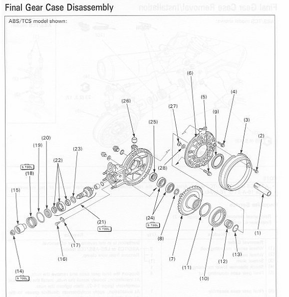
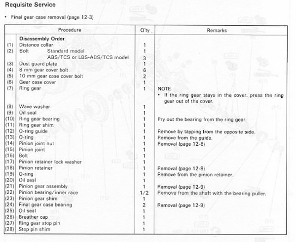
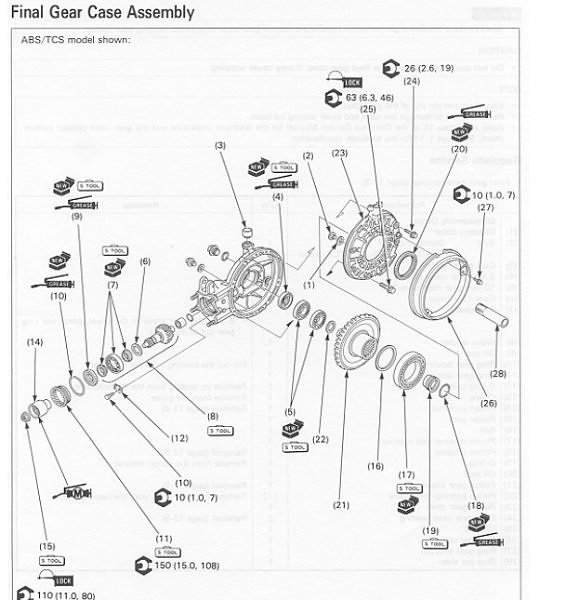
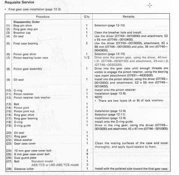
Last post by KoTAOW - February 11, 2012, 04:41:08 PMDriveshaft and U-Joint Replacement ( ST1100 ) - Part 4
Honda Service Manual, Chapter 12
#97
ST1100 Archive of Wisdom / Re: Driveshaft and U-Joint Rep...
Last post by KoTAOW - February 11, 2012, 04:40:37 PMDriveshaft and U-Joint Replacement ( ST1100 ) - Part 3
I had a short "test route" in mind for the shakedown but, somehow, kept missing my turnoff.
It is silky smooth! Oh Boy! I do not remember it ever being so completely without vibration of any sort as it was today. Me thinks that the driveshaft was on its way out long before I got my hands on the beaSTie. It is also quieter than it was... at 100+ km/h I cannot hear the engine at all, even dipping my head down to the tank, out of the airstream, just the whirring of the cams, no induction noise, nothing. It was never like that before.
Gear changes are waaaaay smoother with no obvious lash in the drivetrain. Huh! Who knew??
Checked the drivetrain lash (bike in 1st gear on the center-stand, rotate wheel in each direction until it will not turn any more) and got a measurement of 18.3mm on the wheel hub. Previously it was 20.1mm.
Ok, that's it! I am mobile again. Thanks for watching this program.
~~~
A couple of weeks on....
Still enjoying the nice smooth vibration less ride but I thought I would post a couple of observations...
As previously noted, the gearbox operation seems to be quite a bit better than prior to the repairs and continues to be so.
In my 20/20 hindsight analysis of possible symptoms, I had noted a "tunk" sound that occurred just as the clutch was transferring power to the rear wheel. I had also noted that others had had this sound as well but nobody had found the cause but suspected things like the wheel cush-drive. Well, I have to report that the "tunk" sound has not shown up since the refurbishment of the final drive/driveshaft. Since the only actual part replaced in this episode was the universal joint (I re-used all the other original parts bar a couple of o-rings) then I think it is reasonable to assume that this sound comes from that part. So... if you have the little clunk/tunk sound just as you ease out the clutch prior to starting from a standstill, I would recommend checking the universal joint soon.
~~~
Thank You again for your contribution Allan Bool, STOC #6872
#98
ST1100 Archive of Wisdom / Re: Driveshaft and U-Joint Rep...
Last post by KoTAOW - February 11, 2012, 04:40:03 PMDriveshaft and U-Joint Replacement ( ST1100 ) - Part 2
Continuing...
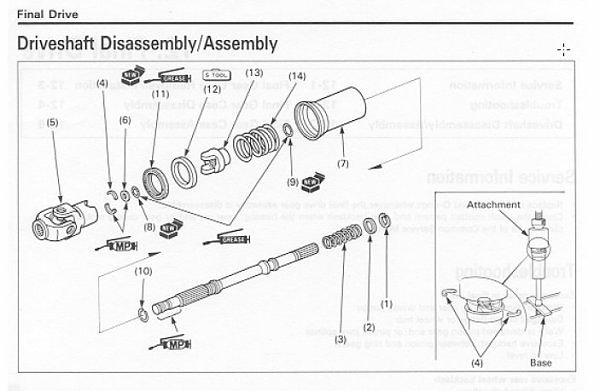
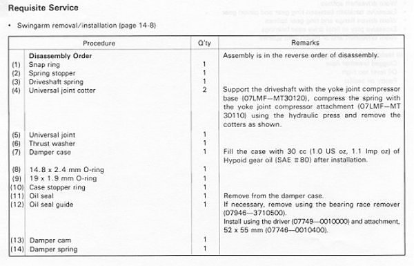
The driveshaft has two little o-rings on it, one to seal the bottom of the "canister" and the other to seal the shaft/universal junction. The originals were in great condition but they have been in there for 20 years, so I decided to replace them.
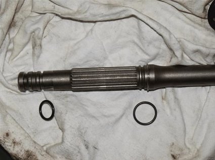
After that it was a case of sliding the cannister back onto the shaft. It just slips down and then seats positively with a bit of a push down over the o-ring. Next bit was to fill the cannister up with 30cc of 80W Hypoid oil and close it off by fitting the universal joint and pushing it down, over the top o-ring and through the seal in the cannister (suitably lubricated). It didn't leak
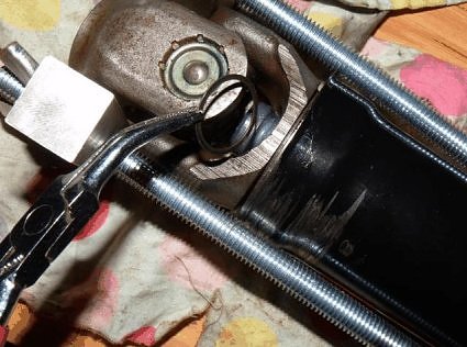
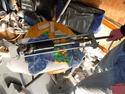
The whole assembly was then set up in my Hi-Tech compressor jig...
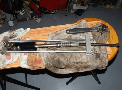
and squeeze the spring so that the shaft is well through.
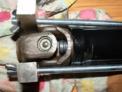
Ready to receive the cotters and thrust washer.
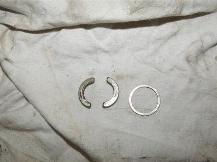
First to go in is the thrust washer.
and then the cotters.
so that it looks like this...
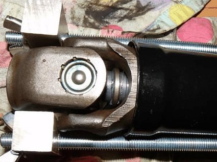
and then release the spring tension so that the universal joint is now locked in place.
I took the completed unit, placed the final drive end on a block of wood and gave the top of the universal joint a couple of taps with a heavy rubber mallet to ensure that everything was seated nicely.
~~~
Next thing was to fill up the pinion cup with moly grease.
I'm not sure how well that went, but there is plenty in there :-)
Next, fit the new seal on the pinion shaft (it is a VERY tight fit) and apply moly grease in the right places and normal lithium based bearing grease to the seal outer.
and fill the other end of the coupling (where the driveshaft fits) with more moly grease.
After that, the whole thing was assembled - the pinion, that is :-) and put to one side while the swingarm bearings were fitted and the swingarm reinstalled into the bike. I'm pretty sure that you don't need pics for this and later bits as many have already done it before and the manual covers it fairly well.
Tomorrow, it is final drive alignment time and reassemble the bike for the big test ride.
~~~
Final drive alignment went ok but Dayum, those four nuts are hard to do with a torque wrench ( I finished up swinging on a 14mm ROE spanner until I could feel it bending and considered them "tight". I all but pulled the bike down on top of myself a couple of times during this procedure. I need to find a better way to do it.
Final drive was topped off (re-filled), all shock mount bolts checked and tightened, tyres pumped up to spec and the speedometer drive replaced on the front (I had a similar but different geared version on there for WOF purposes) and finally started her up.
It took three goes to get her to catch and run... a little rough but soon smoothed out. Tried the gearbox (crunch!!!!) while on the center-stand and checked for the vibration that got me started on this in the first place - none!
~~~
Time to ride.....
#99
ST1100 Archive of Wisdom / Driveshaft and U-Joint Replace...
Last post by KoTAOW - February 11, 2012, 04:39:03 PMSubmitted by Allan Bool, STOC #6872
Original article can be found here: http://www.my-mc.com/messages/1/131530.html?1281757931
~~~
After trying to find the source of the "chattering" sound on my dear old ST, I have come to the conclusion that the culprit is the driveshaft. Searching the archives has turned up a couple of similar instances to mine but what I am trying to determine is the actual replacement procedure.
The workshop manual (Honda) seems to be indicating that just about everything at the rear of the machine must come off before the driveshaft, U-joints, bearings/seals etc. can be accessed. Looking at the way the beast is built, I'm not so sure that this is the case but before I go ahead with pulling things to bits I thought that I would check with the folks, here, if the shaft replacement can be done with the swingarm still in place.
~~~
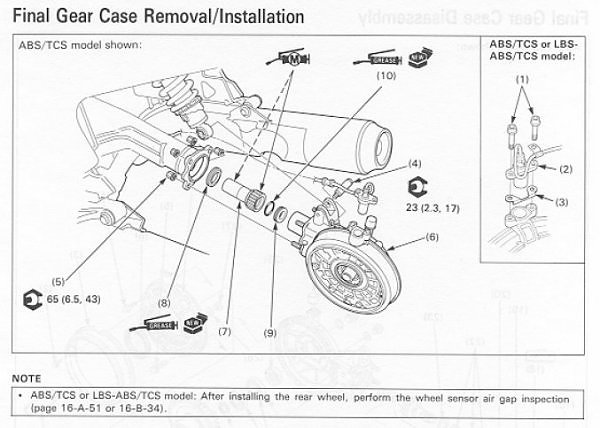
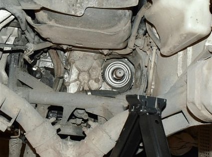
The final drive case is off and the answer is ...NO, you cannot take out the driveshaft without removing the swingarm.
First impressions are as follows:
The four nuts that hold the final drive to the swingarm were done up mighty tight (book says 43 lb/ft), my calibrated spanner arm says 143!! Holy smoke were they tight! They were not done up evenly, either... I am getting suspicious.
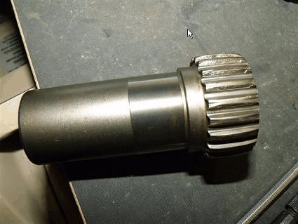
Initial inspection shows minimal lubrication on the splines of the shaft and it has gone hard. A kind of rust colored as well. Surprisingly, the splines appear to still be in good condition. The drive coupling (that goes into the final drive) came out easily by hand. The seal is very soft and distorted. There is a ton of grease in there, not sure of what it is but not the black Moly-type grease I expected. Detailed inspection will be carried out later, after everything is out.
Right, off to go figure out how to pull the swingarm without special tool 07908-4690003.
~~~
Swingarm is now out, the locknut was not particularly tight and I was able to use a pin punch and 14oz hammer to tap it around a quarter turn. Almost no damage to the sharp edge of the locknut. The pivot bolt was also quite easy to undo, it had not been done up particularly tight. The pivot on the RHS however, was done up to a bazillion kg/m and I needed to lean very hard on my 2' long torque wrench to get it undone.
After a bit of wriggling, pulling the driveshaft rearwards to release it from the gearbox output spline and then shifting it all to the left (make sure the rubber boot is off the seat at the front as well) it came out. The splines were dry!
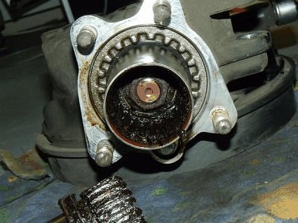
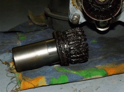
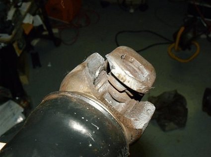
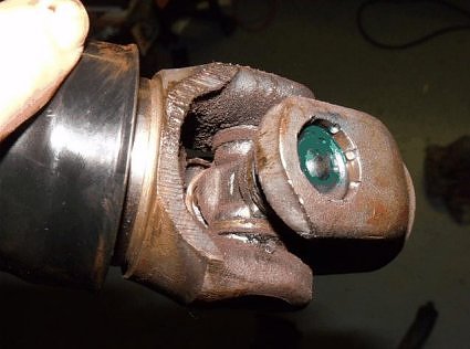
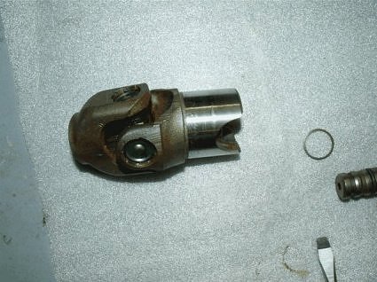
Pull the driveshaft out of the tunnel and the problem is obvious - the universal joint has destroyed itself! I will get some pictures and post up later. It looks as though this has been worn out/damaged for some time. Amazing that it held together and the bike was still ride able.
~~~
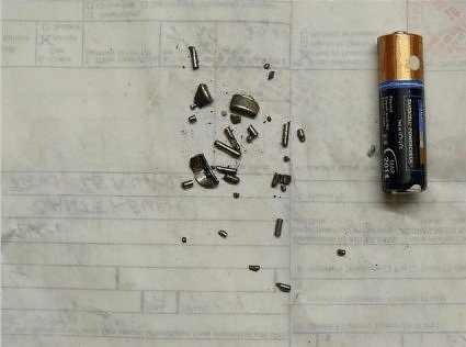
Ok, I have had a bit of a look around in there - lots of metal filings/swarf and a few munched up rollers found inside the driveshaft tunnel - it is a mess in there. I have taken a few photos which I will add to this post. I don't think they need too many comments.
~~~
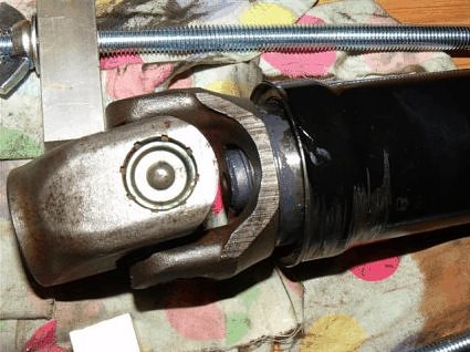
Now we move on to the driveshaft universal itself...
~~~
My bike has 280,000 km on it. I have a strong suspicion that this unit has been apart before and that parts have been replaced. Who ever did the work was not too fussy about the lubing of splines! I also wonder if the final drive alignment was carried out correctly and that has resulted in the premature wear on the universal joint (if the shaft has been replaced - it may not have). Whatever the reason, I would caution all those with bikes that are getting up there in the miles to check these things out.
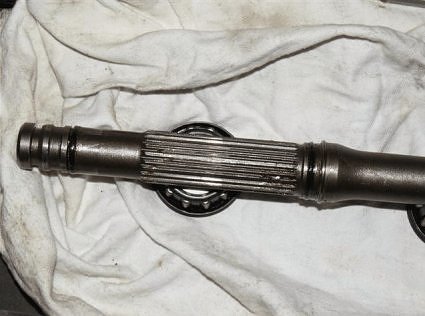
The output splines do not look to have suffered unduly but I have yet to clean the area down and inspect closely. The output shaft bearing feels to be in great condition and the seal is not leaking. It appears that all the forces involved were directed more to the rear of the splined coupling to the gearbox :-)
Yes, once the swingarm is out of the bike, just reach in, grab the shaft coupling and pull it out. The whole assembly rotates inside the tunnel supported only at the Universal joint and the splined coupling to the final drive case at the other end. The only reason the shaft cannot be extracted from the rear of the tunnel is a thin "baffle" just a few cm in from the "south end" of the tunnel. Nothing is supposed to touch the sides (mine has).
Because of the huge amount of metal filings and junk spread around inside the tunnel (you can see the sort of thing I'm talking about in some of the photos), I don't think that I will bother to do a refurbishment but try to obtain a good second-hand item. I will probably attempt dis-assembly at a later stage just for the sake of seeing what other wear and tear is obvious and to determine just how hard it is to do .
~~~
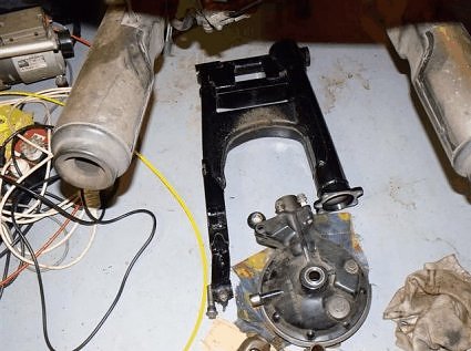
This pic is just as the swingarm came off the bike. The driveshaft is still inside the tunnel and the whole unit has been placed on the floor. It was kinda dark in the garage so I just put the camera on the ground and took a photo looking straight up the tunnel. Here it is.....
~~~
A replacement driveshaft has been obtained from Don Cortez and it arrived a few days ago. It would seem that the package got wet at some stage because it arrived with some nice, new rust (bright orange) all over it :-( I have been cleaning it up in preparation for installation and during the process, I turned the shaft from being vertical with the damper housing at the bottom to having the housing at the top... and something inside rattled
I can continue to invert the shaft and whatever it is inside rattles up and down each time. My old one doesn't do this.
I have looked at the diagram of the internals of the damper unit and can see nothing in there that would move and, besides this, isn't there supposed to be 30cc of SAE 80 Hypoid oil in there? That should, surely (don't call me Shirley), stop anything from rattling?? Any thoughts folks?
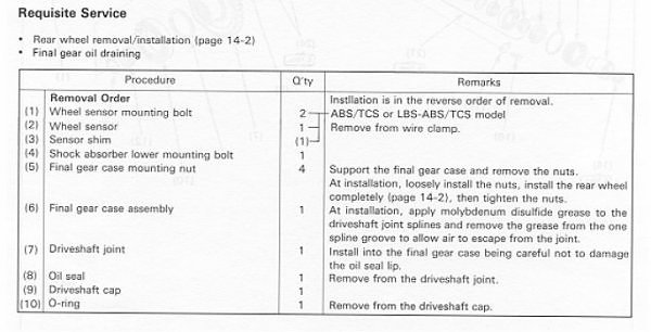
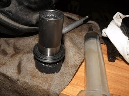
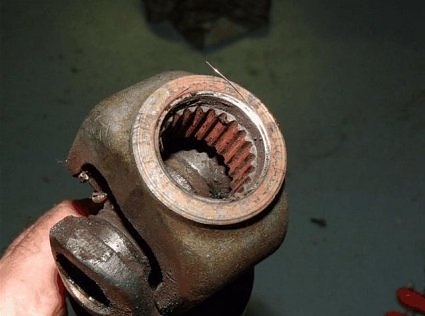
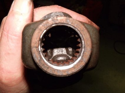
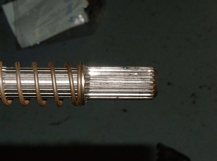
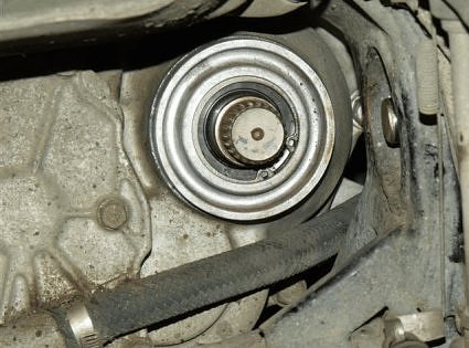
Onwards... to the driveshaft coupling (the bit that the shaft splines go into at the final drive. The seal on mine was pretty sloppy and allowing grease to come past the outside edge of the seal. So out it came and when I went to remove the seal from the coupling I found it stuck fast to the shaft! Eventually I managed to prise it off and then cleaned up the bits. The splined end of the coupling looks like this.....
The grease that is supposed to be in that part is Molybdenum Disulfide grease, according to the Honda manual. Well, the stuff that is in mine is NOT that. It is brown in color and when thinned out by some petrol for cleaning, gives me the impression that it is rust (iron oxide) coloured, certainly not the dark black of the Moly grease that I'm used to seeing. The wear on the splines suggests that the grease in there is not doing a very good job.
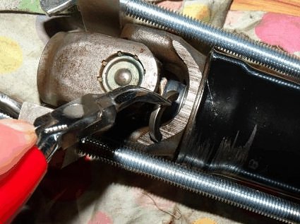
After a bit of thought and a couple of false starts a simple but effective system was devised to start the process off - that of removing the universal joint locking cotters by compressing the big spring inside and pushing the joint down the shaft to make room for their removal.
Once the cotters were taken out, the compression was released and the universal joint pulled off the shaft.
The "cannister" that contains the rest of the unit was then taken off the shaft (it needed a tap on the shaft with a rubber mallet to break the bottom seal).
In all, it was not a difficult job to get it this far.
Both units were done at the same time and there were obvious differences inside.
The original unit (done first) came apart easily and still contained all (as far as I can tell) of the 80W oil. The metal parts were still bright and shining once the oil was cleaned off. The replacement shaft was still fairly easy to dismantle but there was only a trace of oil inside (a smear) and it was pretty gunked up with some rust and who knows what else that had formed a stiff, paste-like substance that covered many of the parts inside. Oh.. the bit that rattled was, as I suspected, the "Stopper, Damper Lifter" (see above post) moving up and down the shaft. It is all a bit dry and yukky in there.
This was a bit discouraging so I didn't proceed any further with disassembly.
The "new" universal joint was cleaned up with some 600 grit wet and dry paper (wet) to get rid of the surface rust and some pitting near the seal area and it will be fitted to the original shaft and damper mechanism after it has been thoroughly cleaned and re-lubricated.
The saga continues....
All parts have now arrived (the odd new bits required) and all has awaited some motivation and warmer temps in the garage :-)
This part is more cleaning and inspection, starting with the swingarm. Cleaning was a tad tedious with 20 years of tarred stones to remove from awkward places, the bearings to remove, clean and inspect and the inside of the driveshaft tunnel to clear out. Just grungy work, nothing special... but the amount of debris removed from inside the tunnel was amazing!
The swingarm, itself, is in excellent condition with only a small amount of paint gone from an area in front of where the tyre fits. It has no rust or (extra) holes - good to go. I may put some abrasion resistant tape over that area, I think paint would be gone pretty quickly.
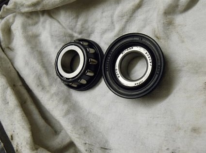
The swingarm pivot bearings were cleaned up - they are a work of art, complete with integral seals. They will need new grease before installation.
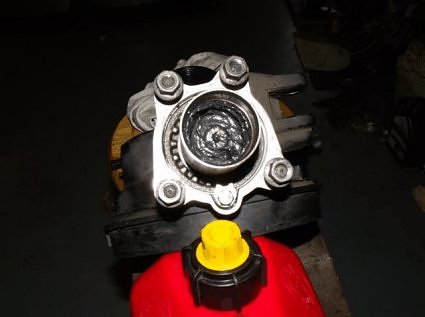
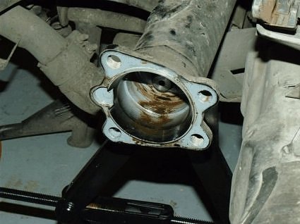
After that, attention turned to the "pinion cup" in the final drive. I had mentioned that when I pulled the pinion coupling out originally, that the grease was a brown (rust) colour and so was the stuff inside.
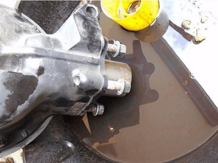
Deeper down in the "cup" was a more solid grease that I can only describe as "gunk". It has the consistency of sticky mud with a tinge of brown colour. I suspect that it is original moly paste but I'm not sure.

Once I had scraped out as much as I could, I poured a little gasoline in to thin out the muck and make it easier to wipe out with a rag... but the gas disappeared! Where the •••• did that go??? I tipped the drive down to empty the cup and a little brown fluid dripped out into the cleaning dish and then it was followed by a clear, viscous fluid - my 80W Hypoid oil from inside the "pumpkin".
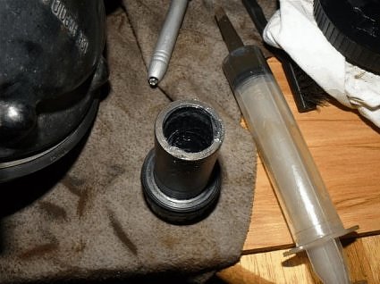
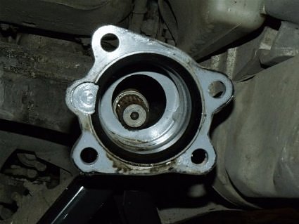
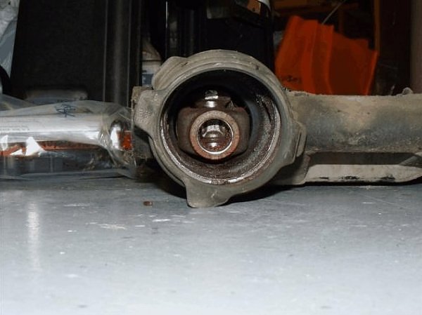
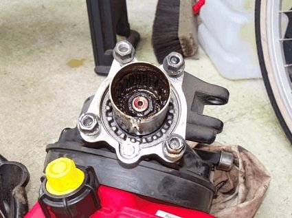
Once the oil had drained, I set about cleaning out the rest, finally getting it to look like this...
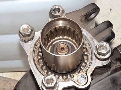
... and down at the bottom I spy two small holes that obviously go right through to the drive housing. You can see one of them in the picture.
I checked the Honda manual for any mention of this little surprise but found nothing. If anyone knows how you stop the hypoid oil from mixing with the grease in this "cup" I would like to hear about it. Hmmmmm.... !
After that, it was on to checking and cleaning the gearbox output shaft splines.
and the pinion drive internal spline. Both were dry and devoid of any form of lubrication, either old or new, but both appear to have suffered little because of that lack - <whew>
That just about does it for now... next step will be applying grease/oils/paste to the appropriate areas and then (gasp) assembly!
~~~
The mystery of the two little holes in the pinion cup... it seems that others know about this but where did the info come from??
Swingarm Removal and Replacement
~~~
Comments by Mark Frost, STOC #1162:
Cover the holes at the bottom of the final drive cup with 3% moly-fortified
grease, but do NOT bring the grease all the way up the wall of the cup, or
it will foul the oil seal (which should be lubed with standard bearing
grease, not the 3% moly.)
I tore down the driveshaft on my '00 ABS at 17,000 miles just to see how
things were wearing, and to re-lube it with high performance synthetic
greases. I had found other areas on the bike that were not greased
properly, and I wanted to be sure. I've posted before that I found the cup
grease applied in a precise fashion, very oriental, really, as it was placed
only at the bottom-half of the cup and *thoroughly* sealed the two holes.
My own opinion is that Honda does this to prevent a low-fluid condition from
developing inside the drive housing. With only 6 ounces available on
dry-fill, there's not much lubricant there to work with if you're already
low and some moves forward into the cup.
Moly Paste-60 is used on the splines leaving the engine and in the U-joint
itself. The 3% stuff also goes on the male splines of the driveshaft
itself, where the connecting piece mates. The old grease should always be
removed from parts before applying the new, or a lack of lubrication may
result. Greases of different base stocks are often not compatible.
U.S.-based liSTers can't order the special tools necessary to compress the
driveshaft to disassemble the U-joint, but our Canadian brethren can. Here
are the part numbers:
07LMF-MT30110 Yoke Joint Compressor
07LMF-MT30120 Yoke Joint Compressor Base
The base seems like an optional item, as any good wood-blocked vice should
work.
Last step is to re-align the final drive by fully mounting and torquing the
rear wheel, and then tightening the four bolts holding it on. Finger-tight
on the four bolts to start is fine.
~~~
Original article can be found here: http://www.my-mc.com/messages/1/131530.html?1281757931
~~~
Driveshaft and U-Joint Replacement ( ST1100 ) - Part 1
After trying to find the source of the "chattering" sound on my dear old ST, I have come to the conclusion that the culprit is the driveshaft. Searching the archives has turned up a couple of similar instances to mine but what I am trying to determine is the actual replacement procedure.
The workshop manual (Honda) seems to be indicating that just about everything at the rear of the machine must come off before the driveshaft, U-joints, bearings/seals etc. can be accessed. Looking at the way the beast is built, I'm not so sure that this is the case but before I go ahead with pulling things to bits I thought that I would check with the folks, here, if the shaft replacement can be done with the swingarm still in place.
~~~
The final drive case is off and the answer is ...NO, you cannot take out the driveshaft without removing the swingarm.
First impressions are as follows:
The four nuts that hold the final drive to the swingarm were done up mighty tight (book says 43 lb/ft), my calibrated spanner arm says 143!! Holy smoke were they tight! They were not done up evenly, either... I am getting suspicious.
Initial inspection shows minimal lubrication on the splines of the shaft and it has gone hard. A kind of rust colored as well. Surprisingly, the splines appear to still be in good condition. The drive coupling (that goes into the final drive) came out easily by hand. The seal is very soft and distorted. There is a ton of grease in there, not sure of what it is but not the black Moly-type grease I expected. Detailed inspection will be carried out later, after everything is out.
Right, off to go figure out how to pull the swingarm without special tool 07908-4690003.
~~~
Swingarm is now out, the locknut was not particularly tight and I was able to use a pin punch and 14oz hammer to tap it around a quarter turn. Almost no damage to the sharp edge of the locknut. The pivot bolt was also quite easy to undo, it had not been done up particularly tight. The pivot on the RHS however, was done up to a bazillion kg/m and I needed to lean very hard on my 2' long torque wrench to get it undone.
After a bit of wriggling, pulling the driveshaft rearwards to release it from the gearbox output spline and then shifting it all to the left (make sure the rubber boot is off the seat at the front as well) it came out. The splines were dry!
Pull the driveshaft out of the tunnel and the problem is obvious - the universal joint has destroyed itself! I will get some pictures and post up later. It looks as though this has been worn out/damaged for some time. Amazing that it held together and the bike was still ride able.
~~~
Ok, I have had a bit of a look around in there - lots of metal filings/swarf and a few munched up rollers found inside the driveshaft tunnel - it is a mess in there. I have taken a few photos which I will add to this post. I don't think they need too many comments.
~~~
Now we move on to the driveshaft universal itself...
~~~
My bike has 280,000 km on it. I have a strong suspicion that this unit has been apart before and that parts have been replaced. Who ever did the work was not too fussy about the lubing of splines! I also wonder if the final drive alignment was carried out correctly and that has resulted in the premature wear on the universal joint (if the shaft has been replaced - it may not have). Whatever the reason, I would caution all those with bikes that are getting up there in the miles to check these things out.
The output splines do not look to have suffered unduly but I have yet to clean the area down and inspect closely. The output shaft bearing feels to be in great condition and the seal is not leaking. It appears that all the forces involved were directed more to the rear of the splined coupling to the gearbox :-)
Yes, once the swingarm is out of the bike, just reach in, grab the shaft coupling and pull it out. The whole assembly rotates inside the tunnel supported only at the Universal joint and the splined coupling to the final drive case at the other end. The only reason the shaft cannot be extracted from the rear of the tunnel is a thin "baffle" just a few cm in from the "south end" of the tunnel. Nothing is supposed to touch the sides (mine has).
Because of the huge amount of metal filings and junk spread around inside the tunnel (you can see the sort of thing I'm talking about in some of the photos), I don't think that I will bother to do a refurbishment but try to obtain a good second-hand item. I will probably attempt dis-assembly at a later stage just for the sake of seeing what other wear and tear is obvious and to determine just how hard it is to do .
~~~
This pic is just as the swingarm came off the bike. The driveshaft is still inside the tunnel and the whole unit has been placed on the floor. It was kinda dark in the garage so I just put the camera on the ground and took a photo looking straight up the tunnel. Here it is.....
~~~
A replacement driveshaft has been obtained from Don Cortez and it arrived a few days ago. It would seem that the package got wet at some stage because it arrived with some nice, new rust (bright orange) all over it :-( I have been cleaning it up in preparation for installation and during the process, I turned the shaft from being vertical with the damper housing at the bottom to having the housing at the top... and something inside rattled
I can continue to invert the shaft and whatever it is inside rattles up and down each time. My old one doesn't do this.
I have looked at the diagram of the internals of the damper unit and can see nothing in there that would move and, besides this, isn't there supposed to be 30cc of SAE 80 Hypoid oil in there? That should, surely (don't call me Shirley), stop anything from rattling?? Any thoughts folks?
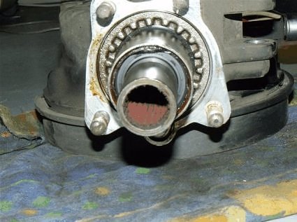
Onwards... to the driveshaft coupling (the bit that the shaft splines go into at the final drive. The seal on mine was pretty sloppy and allowing grease to come past the outside edge of the seal. So out it came and when I went to remove the seal from the coupling I found it stuck fast to the shaft! Eventually I managed to prise it off and then cleaned up the bits. The splined end of the coupling looks like this.....
The grease that is supposed to be in that part is Molybdenum Disulfide grease, according to the Honda manual. Well, the stuff that is in mine is NOT that. It is brown in color and when thinned out by some petrol for cleaning, gives me the impression that it is rust (iron oxide) coloured, certainly not the dark black of the Moly grease that I'm used to seeing. The wear on the splines suggests that the grease in there is not doing a very good job.
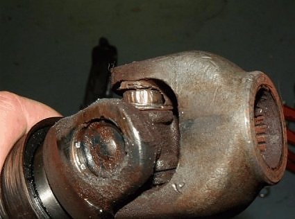
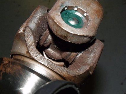
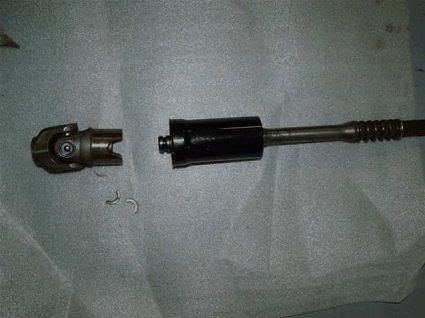
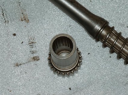
After a bit of thought and a couple of false starts a simple but effective system was devised to start the process off - that of removing the universal joint locking cotters by compressing the big spring inside and pushing the joint down the shaft to make room for their removal.
Once the cotters were taken out, the compression was released and the universal joint pulled off the shaft.
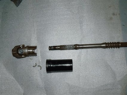
The "cannister" that contains the rest of the unit was then taken off the shaft (it needed a tap on the shaft with a rubber mallet to break the bottom seal).
In all, it was not a difficult job to get it this far.
Both units were done at the same time and there were obvious differences inside.
The original unit (done first) came apart easily and still contained all (as far as I can tell) of the 80W oil. The metal parts were still bright and shining once the oil was cleaned off. The replacement shaft was still fairly easy to dismantle but there was only a trace of oil inside (a smear) and it was pretty gunked up with some rust and who knows what else that had formed a stiff, paste-like substance that covered many of the parts inside. Oh.. the bit that rattled was, as I suspected, the "Stopper, Damper Lifter" (see above post) moving up and down the shaft. It is all a bit dry and yukky in there.
This was a bit discouraging so I didn't proceed any further with disassembly.
The "new" universal joint was cleaned up with some 600 grit wet and dry paper (wet) to get rid of the surface rust and some pitting near the seal area and it will be fitted to the original shaft and damper mechanism after it has been thoroughly cleaned and re-lubricated.
The saga continues....
All parts have now arrived (the odd new bits required) and all has awaited some motivation and warmer temps in the garage :-)
This part is more cleaning and inspection, starting with the swingarm. Cleaning was a tad tedious with 20 years of tarred stones to remove from awkward places, the bearings to remove, clean and inspect and the inside of the driveshaft tunnel to clear out. Just grungy work, nothing special... but the amount of debris removed from inside the tunnel was amazing!
The swingarm, itself, is in excellent condition with only a small amount of paint gone from an area in front of where the tyre fits. It has no rust or (extra) holes - good to go. I may put some abrasion resistant tape over that area, I think paint would be gone pretty quickly.
The swingarm pivot bearings were cleaned up - they are a work of art, complete with integral seals. They will need new grease before installation.
After that, attention turned to the "pinion cup" in the final drive. I had mentioned that when I pulled the pinion coupling out originally, that the grease was a brown (rust) colour and so was the stuff inside.
Deeper down in the "cup" was a more solid grease that I can only describe as "gunk". It has the consistency of sticky mud with a tinge of brown colour. I suspect that it is original moly paste but I'm not sure.
Once I had scraped out as much as I could, I poured a little gasoline in to thin out the muck and make it easier to wipe out with a rag... but the gas disappeared! Where the •••• did that go??? I tipped the drive down to empty the cup and a little brown fluid dripped out into the cleaning dish and then it was followed by a clear, viscous fluid - my 80W Hypoid oil from inside the "pumpkin".
Once the oil had drained, I set about cleaning out the rest, finally getting it to look like this...
... and down at the bottom I spy two small holes that obviously go right through to the drive housing. You can see one of them in the picture.
I checked the Honda manual for any mention of this little surprise but found nothing. If anyone knows how you stop the hypoid oil from mixing with the grease in this "cup" I would like to hear about it. Hmmmmm.... !
After that, it was on to checking and cleaning the gearbox output shaft splines.
and the pinion drive internal spline. Both were dry and devoid of any form of lubrication, either old or new, but both appear to have suffered little because of that lack - <whew>
That just about does it for now... next step will be applying grease/oils/paste to the appropriate areas and then (gasp) assembly!
~~~
The mystery of the two little holes in the pinion cup... it seems that others know about this but where did the info come from??
Swingarm Removal and Replacement
~~~
Comments by Mark Frost, STOC #1162:
Cover the holes at the bottom of the final drive cup with 3% moly-fortified
grease, but do NOT bring the grease all the way up the wall of the cup, or
it will foul the oil seal (which should be lubed with standard bearing
grease, not the 3% moly.)
I tore down the driveshaft on my '00 ABS at 17,000 miles just to see how
things were wearing, and to re-lube it with high performance synthetic
greases. I had found other areas on the bike that were not greased
properly, and I wanted to be sure. I've posted before that I found the cup
grease applied in a precise fashion, very oriental, really, as it was placed
only at the bottom-half of the cup and *thoroughly* sealed the two holes.
My own opinion is that Honda does this to prevent a low-fluid condition from
developing inside the drive housing. With only 6 ounces available on
dry-fill, there's not much lubricant there to work with if you're already
low and some moves forward into the cup.
Moly Paste-60 is used on the splines leaving the engine and in the U-joint
itself. The 3% stuff also goes on the male splines of the driveshaft
itself, where the connecting piece mates. The old grease should always be
removed from parts before applying the new, or a lack of lubrication may
result. Greases of different base stocks are often not compatible.
U.S.-based liSTers can't order the special tools necessary to compress the
driveshaft to disassemble the U-joint, but our Canadian brethren can. Here
are the part numbers:
07LMF-MT30110 Yoke Joint Compressor
07LMF-MT30120 Yoke Joint Compressor Base
The base seems like an optional item, as any good wood-blocked vice should
work.
Last step is to re-align the final drive by fully mounting and torquing the
rear wheel, and then tightening the four bolts holding it on. Finger-tight
on the four bolts to start is fine.
~~~
#100
ST1100 Archive of Wisdom / Shorai Lithium Iron Battery ( ...
Last post by KoTAOW - February 11, 2012, 12:36:23 PMInformation and Comments by Tim Shevlin, STOC #1183 and Steve Kelley, STOC #077
Related installation thread with photo's on a 2009 R1200R, BMW: http://www.advrider.com/forums/showthread.php?t=650857
~~~
Links:
Shorai Lithium Batteries Shorai Battery Chargers
Shorai Battery - ST1100 Shorai Battery - ST1300
~~~
Comments by Tim Shevlin: If you're willing to gamble on really new technology, consider replacing your tired battery with a new Shorai. I have been using my new Shorai for a whole month now (!!) and it's still working as advertised. (it is a remarkable product, IMHO) And getting a little weight off of the right side of the ST1300 doesn't hurt either.
Just got an e-notice from Chaparral that features a special on Shorai batteries for less than I paid. (grrrr...) Go for it.
~~~
Comments by Steve Kelly:
Here is the info on what I ordered:
Battery Info
SKU:4897034420111
Product:LFX18A1-BS12
Price: $189.95
Charger Info
SKU: 4897034420289
Product: SHO-BMS01
Price: $79.95
SubTotal: $269.90
Shipping: FedEx Home Delivery $12.03
Tax: $0.00
Total: $281.93
~~~
Be sure to read their FAQ - for instance, you DO NOT want to use an anti-sulfating battery tender.
And I found the following fascinating as well as counter-intuitive:
Question: I hear that lithium crank poorly when it gets cold, is that right?
Answer: Lithium do increase in resistance more as temperature drops, compared to lead-acid. However, they also react to cranking under cold conditions in a much better way. Lead-acid will increase resistance on each subsequent cranking attempt, until it won’t turn over. If your LFX fails to start the engine on first crank, that first crank has warmed the battery, and the second attempt will be much stronger, and so on until you get a good start.
Shorai LFX are much better in cold-weather conditions than other-brand lithium starter batteries, due to our extreme-rate formulation with low resistance. Down to about 20 degrees Fahrenheit (-7C) most users find that they can start normally on first crank. If your headlight comes on at key-ON, it is good for the batteries to flow some current before cranking in cold weather. The suggested headlight-on time before cranking depends on the temperature. If starting at 40f (5C), 30 seconds will help wake the battery and increase cranking performance. If at 0f (-17C), leave the lights on for 4~5 minutes before cranking. The result will be a better first crank, and longer battery life. Any other accessories that can be turned on before cranking can also be used for this purpose, such as heated gear, radio, etc...
It is worth noting that, while the Shorai is 80% lighter than stock, acid free, and can be mounted in any position, it is also about 1/3 the size of a stock battery and must be shimmed into place. I popped for one and a charger direct from Shorai at retail. Not a good deal, but it's for my ST, and I don't have any other children.
~~~
Comments by Dauntless, from ADVRider forum:
Here is what it looks like packed in the foam pieces that you must trim to make it match your original battery:

Here it is compared to my 2009 R1200R's original battery:


Here it is with the foam cut to shim the battery:


The battery is 7 pounds lighter than the original. It is so light that it makes you wonder how it can generate any power.
The battery was a PITA to install because the nut to which the terminal screw attaches falls away and out of reach if you have an accessory wire attached to the battery in addition to the main cable. I had to stick a piece of the foam under the nut in order to keep it in place and within reach of the screw. Here is a comparison of my original battery's pretty robust terminal and the Shorai's terminal:

It would be nice if the nut was taller and the terminal itself was flush with the top of the battery. The way it is now, the leads of my battery cables are angled down to meet the terminal and probably don't have as good of a contact area as it would if the terminal was flush.
Further, the foam pads that shim the battery are exposed to water spray. I don't know how they will hold up or if they will retain water like a sponge.
If I had known that I had to cut foam to make this battery fit and shim the terminal nuts to make them work, I wouldn't have bought this battery. The weight savings isn't that important to me. I think an Odyssey battery would have served my purposes just fine.
Here is a good explanation of the benefits: http://www.novaelectric.com/life.php
Some advantages of the Lithium Ion Phosphate batteries are listed below for reference:
4X higher energy density than lead-acid battery: The gravimetric energy density of the LiFePO4 battery is ~130 Wh/kg, almost four times higher than that of a typical Lead-acid battery, at 35Wh/kg. For the UPS user, this means far greater run times while running on battery, without any space penalty.
Light Weight: Despite the vastly higher energy density, the LiFePO4 battery packs are, in most cases, only 1/3 the weight of conventional lead acid packs. So for applications where weight savings are critical, the use of LiFePO4 batteries can result in significant reductions in overall system weight.
Long Life: LiFePO4 battery packs typically achieve a minimum of 2000 cycles with 70% capacity remaining, with up to 5000 cycle potential. This is equivalent to the 8-12 year expected life the very best sealed, lead acid batteries offer. Further, LiFePO4 batteries do not suffer from the “memory effect†of some conventional lead acid batteries.
Better Voltage Regulation: Unlike the Lead acid battery, the LiFePO4 battery terminal voltage remains relatively constant during high rate discharge. This equates to much better performance during high rate (short time period) discharges, yielding a much better AH performance during this type of application, typical in UPS systems.
Wide Temp Range: LiFePO4 battery packs are typically sold for operation between -20°C to +60°C, charging between -10°C to +60°C, and storage between -40°C to +70°C. This is equivalent to the ranges that only premium sealed, lead acid batteries offer.
Safety with power: Safety is equivalent to or better than the traditional lead acid type, without the risk of explosion or fire outbreak associated with some other new battery technologies. The LiFePO4 battery has hybrid characteristics: it is as safe as the lead-acid battery and as powerful as the lithium ion battery.
A Greener Battery: The eco-friendly LiFePO4 battery packs are recyclable and non-toxic.
Battery Management: All LiFePO4 Batteries are provided with a Battery Management System (BMS) which protects the battery cells within the Nova LiFePO4 Battery pack. The BMS will protect the cells to be sure they do not go outside of the normal limits of Cell voltage of the minimum discharge voltage of 2.8 V, the working voltage of 3.0 V â€" 3.3 V, and the maximum charge voltage of 3.6 V. The BMS also provides short circuit protection which prevents high current in the event of an external short circuit.
~~~
Thank You again to everyone who contributed.
Related installation thread with photo's on a 2009 R1200R, BMW: http://www.advrider.com/forums/showthread.php?t=650857
~~~
Shorai Lithium Iron Battery ( ST1100\ST1300 )
Links:
Shorai Lithium Batteries Shorai Battery Chargers
Shorai Battery - ST1100 Shorai Battery - ST1300
~~~
Comments by Tim Shevlin: If you're willing to gamble on really new technology, consider replacing your tired battery with a new Shorai. I have been using my new Shorai for a whole month now (!!) and it's still working as advertised. (it is a remarkable product, IMHO) And getting a little weight off of the right side of the ST1300 doesn't hurt either.
Just got an e-notice from Chaparral that features a special on Shorai batteries for less than I paid. (grrrr...) Go for it.
~~~
Comments by Steve Kelly:
Here is the info on what I ordered:
Battery Info
SKU:4897034420111
Product:LFX18A1-BS12
Price: $189.95
Charger Info
SKU: 4897034420289
Product: SHO-BMS01
Price: $79.95
SubTotal: $269.90
Shipping: FedEx Home Delivery $12.03
Tax: $0.00
Total: $281.93
~~~
Be sure to read their FAQ - for instance, you DO NOT want to use an anti-sulfating battery tender.
And I found the following fascinating as well as counter-intuitive:
Question: I hear that lithium crank poorly when it gets cold, is that right?
Answer: Lithium do increase in resistance more as temperature drops, compared to lead-acid. However, they also react to cranking under cold conditions in a much better way. Lead-acid will increase resistance on each subsequent cranking attempt, until it won’t turn over. If your LFX fails to start the engine on first crank, that first crank has warmed the battery, and the second attempt will be much stronger, and so on until you get a good start.
Shorai LFX are much better in cold-weather conditions than other-brand lithium starter batteries, due to our extreme-rate formulation with low resistance. Down to about 20 degrees Fahrenheit (-7C) most users find that they can start normally on first crank. If your headlight comes on at key-ON, it is good for the batteries to flow some current before cranking in cold weather. The suggested headlight-on time before cranking depends on the temperature. If starting at 40f (5C), 30 seconds will help wake the battery and increase cranking performance. If at 0f (-17C), leave the lights on for 4~5 minutes before cranking. The result will be a better first crank, and longer battery life. Any other accessories that can be turned on before cranking can also be used for this purpose, such as heated gear, radio, etc...
It is worth noting that, while the Shorai is 80% lighter than stock, acid free, and can be mounted in any position, it is also about 1/3 the size of a stock battery and must be shimmed into place. I popped for one and a charger direct from Shorai at retail. Not a good deal, but it's for my ST, and I don't have any other children.
~~~
Comments by Dauntless, from ADVRider forum:
Here is what it looks like packed in the foam pieces that you must trim to make it match your original battery:
Here it is compared to my 2009 R1200R's original battery:
Here it is with the foam cut to shim the battery:
The battery is 7 pounds lighter than the original. It is so light that it makes you wonder how it can generate any power.
The battery was a PITA to install because the nut to which the terminal screw attaches falls away and out of reach if you have an accessory wire attached to the battery in addition to the main cable. I had to stick a piece of the foam under the nut in order to keep it in place and within reach of the screw. Here is a comparison of my original battery's pretty robust terminal and the Shorai's terminal:
It would be nice if the nut was taller and the terminal itself was flush with the top of the battery. The way it is now, the leads of my battery cables are angled down to meet the terminal and probably don't have as good of a contact area as it would if the terminal was flush.
Further, the foam pads that shim the battery are exposed to water spray. I don't know how they will hold up or if they will retain water like a sponge.
If I had known that I had to cut foam to make this battery fit and shim the terminal nuts to make them work, I wouldn't have bought this battery. The weight savings isn't that important to me. I think an Odyssey battery would have served my purposes just fine.
Here is a good explanation of the benefits: http://www.novaelectric.com/life.php
Some advantages of the Lithium Ion Phosphate batteries are listed below for reference:
4X higher energy density than lead-acid battery: The gravimetric energy density of the LiFePO4 battery is ~130 Wh/kg, almost four times higher than that of a typical Lead-acid battery, at 35Wh/kg. For the UPS user, this means far greater run times while running on battery, without any space penalty.
Light Weight: Despite the vastly higher energy density, the LiFePO4 battery packs are, in most cases, only 1/3 the weight of conventional lead acid packs. So for applications where weight savings are critical, the use of LiFePO4 batteries can result in significant reductions in overall system weight.
Long Life: LiFePO4 battery packs typically achieve a minimum of 2000 cycles with 70% capacity remaining, with up to 5000 cycle potential. This is equivalent to the 8-12 year expected life the very best sealed, lead acid batteries offer. Further, LiFePO4 batteries do not suffer from the “memory effect†of some conventional lead acid batteries.
Better Voltage Regulation: Unlike the Lead acid battery, the LiFePO4 battery terminal voltage remains relatively constant during high rate discharge. This equates to much better performance during high rate (short time period) discharges, yielding a much better AH performance during this type of application, typical in UPS systems.
Wide Temp Range: LiFePO4 battery packs are typically sold for operation between -20°C to +60°C, charging between -10°C to +60°C, and storage between -40°C to +70°C. This is equivalent to the ranges that only premium sealed, lead acid batteries offer.
Safety with power: Safety is equivalent to or better than the traditional lead acid type, without the risk of explosion or fire outbreak associated with some other new battery technologies. The LiFePO4 battery has hybrid characteristics: it is as safe as the lead-acid battery and as powerful as the lithium ion battery.
A Greener Battery: The eco-friendly LiFePO4 battery packs are recyclable and non-toxic.
Battery Management: All LiFePO4 Batteries are provided with a Battery Management System (BMS) which protects the battery cells within the Nova LiFePO4 Battery pack. The BMS will protect the cells to be sure they do not go outside of the normal limits of Cell voltage of the minimum discharge voltage of 2.8 V, the working voltage of 3.0 V â€" 3.3 V, and the maximum charge voltage of 3.6 V. The BMS also provides short circuit protection which prevents high current in the event of an external short circuit.
~~~
Thank You again to everyone who contributed.